
Multiple technology flow sensor

Inactive Publication Date: 2005-04-21
FESTO AG & CO KG
View PDF39 Cites 19 Cited by
  • Summary
  • Abstract
  • Description
  • Claims
  • Application Information

AI Technical Summary

Benefits of technology

[0009] It is an object of the present invention to provide a multiple technology flow sensor and a method for determining flow rate that have generic applicability and do not require substantial modification over a wide range of pressure, temperature, and types of media.
[0011] It is yet another object of the present invention to provide a multiple technology flow sensor and method for determining flow rate that are able to simultaneously or sequentially characterize physical characteristics of gaseous media, such as temperature and pressure, which may then be used to compensate and significantly improve the accuracy of flow rate measurements.
[0012] It is still another object of the present invention to provide a multiple technology flow sensor and method for determining flow rate that reduce the size, cost, and space requirements of the sensor by incorporating multiple sensors within a single housing.
[0013] It is a further object of the present invention to provide a multiple technology flow sensor and method for determining flow rate that simplify the manufacture of the sensor.
[0014] It is still a further object of the present invention to provide a multiple technology flow sensor and method for determining flow rate that substantially eliminate external wiring and supplemental interfacing hardware requirements.
[0015] It is yet a further object of the present invention to provide a multiple technology flow sensor and method for determining flow rate that significantly increase measurement accuracy by substantially reducing the effect of environmental factors on flow rate measurements.

Problems solved by technology

However, the requirement of multiple sensors substantially increases the rate of failure and cost of installation.
Thus, application of inferential flow measurement principles becomes practical in only limited circumstances.
These sensors are often located at significant distances from each other, which necessitate the use of external wiring and / or interface assemblies, as well as substantially increasing the size, cost, and space requirements of the system.
In addition, most flow rate sensors do not compensate for the effect of temperature or pressure in the flow rate measurement.
Accordingly, such measurements may be highly inaccurate, particularly when taken over a wide range of conditions.

Method used


Image

  • Multiple technology flow sensor
  • Multiple technology flow sensor
  • Multiple technology flow sensor

Examples


Embodiment Construction

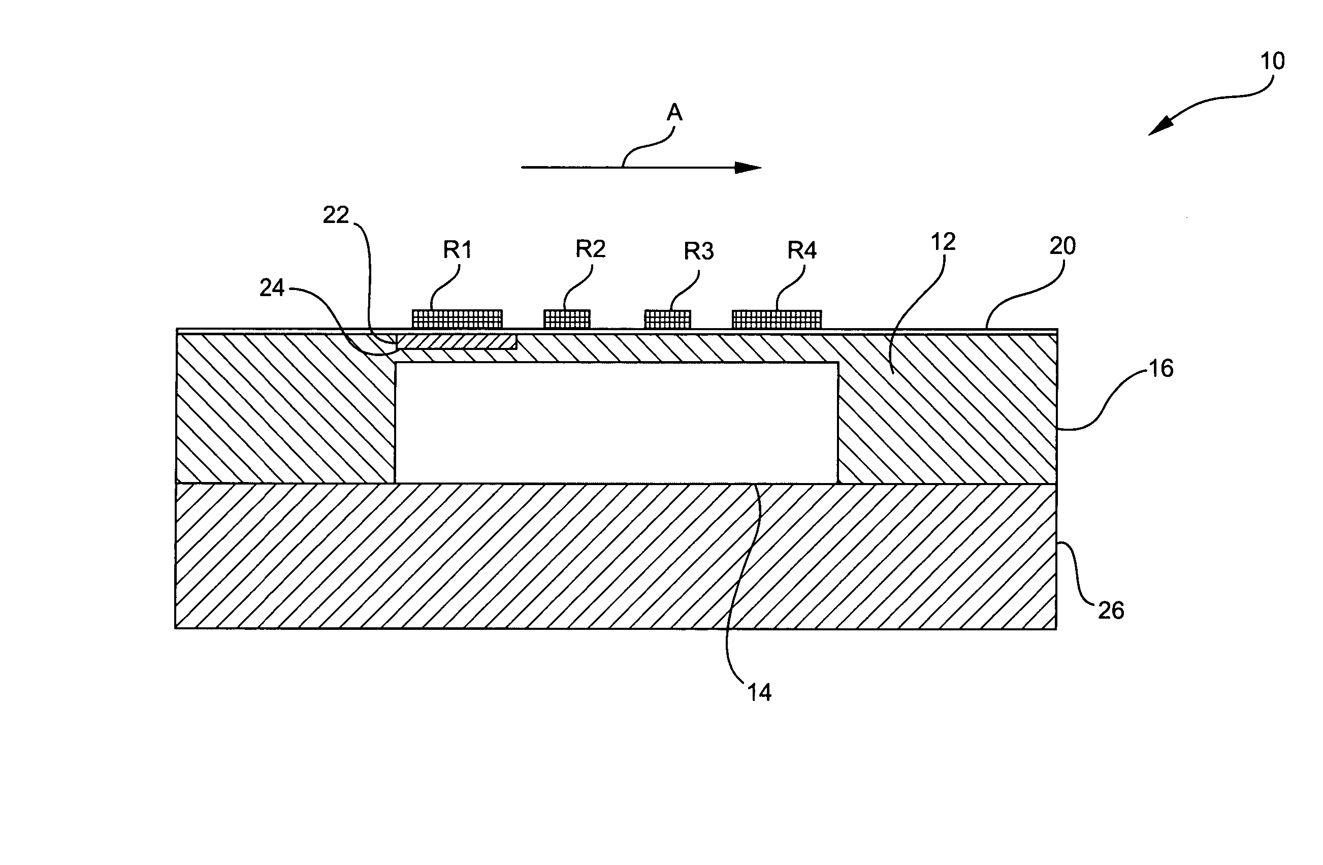
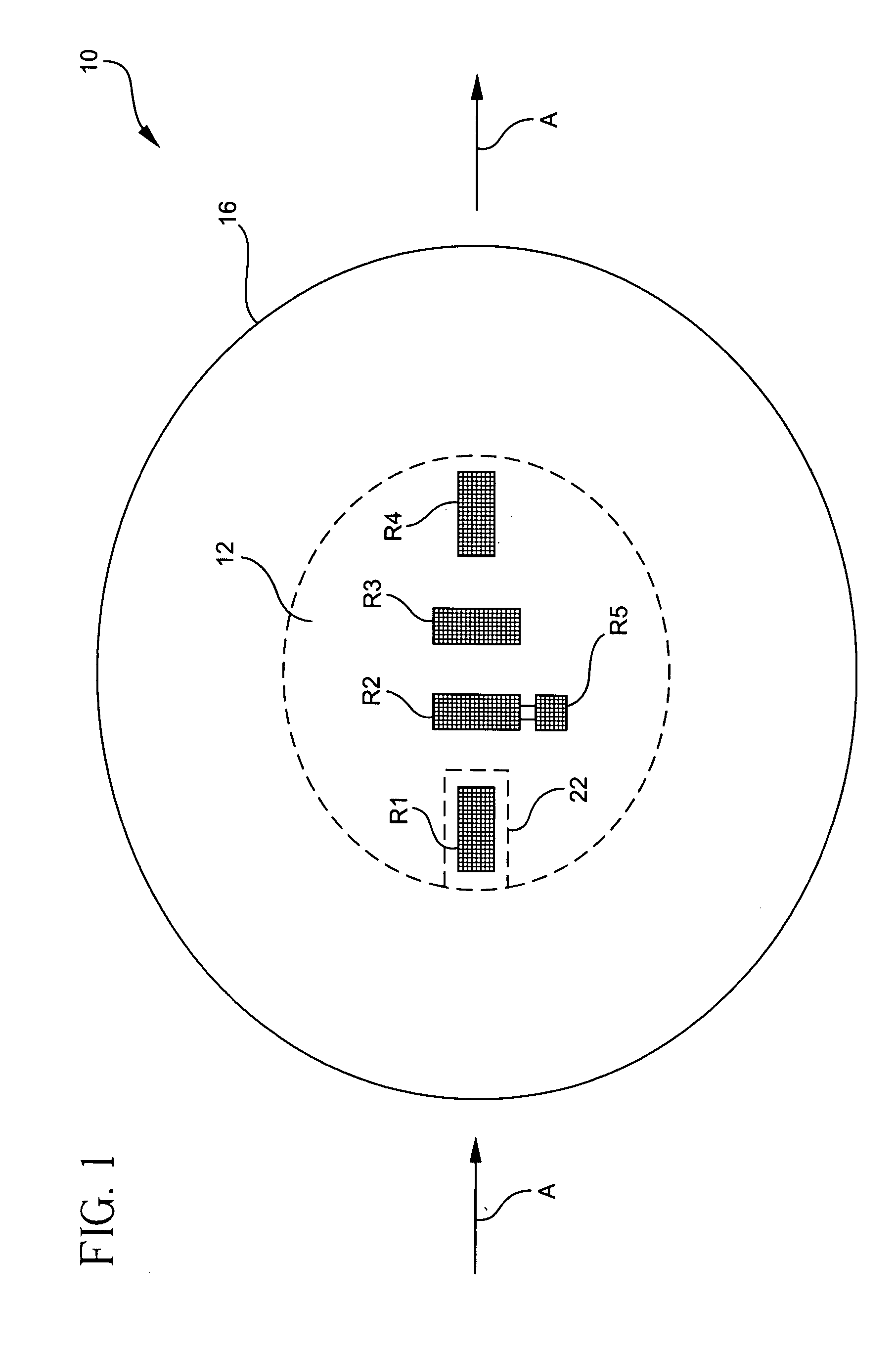
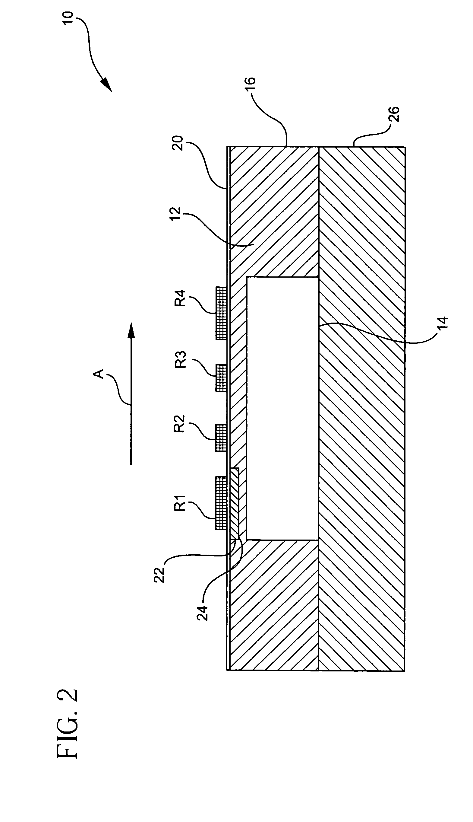
[0026] In order to measure the flow rate of media, which is the volume or mass per unit time, additional physical characteristics, such as temperature and pressure, are preferably used to enhance the precision of the flow measurement. A multiple technology flow sensor formed in accordance with the present invention measures the flow of media, such as a gas, liquid, slurry, composition, and the like, but preferably air. The sensor detects the amount of electrical current required to maintain a body at a uniform temperature, and compensates this measurement with temperature and pressure information, which is also detected simultaneously or sequentially by the sensor.

[0027]FIG. 1 shows a top view of a preferred embodiment of the flow sensor 10, which includes a Wheatstone bridge disposed on a wafer 16. The Wheatstone bridge preferably includes four resistors or sensing elements R1, R2, R3, and R4, at least a portion of which measure the flow rate (O), pressure (p), and temperature (T)...


PUM


Abstract

A flow sensor includes sensors connected to a flexible membrane. The sensors detect ambient temperature, pressure, and flow rate of a medium. A method of sensing flow rate includes providing the flexible membrane; coupling the plurality of sensors to the flexible membrane; and detecting ambient temperature, pressure, and flow rate of the medium by the sensors. A flow sensing system includes the flow sensor, an operational amplifier, and a closed loop controller. The sensors are connected in a Wheatstone bridge configuration. The operational amplifier is connected to the Wheatstone bridge and outputs a pressure signal representative of the pressure of the medium. The closed loop controller is connected to the operational amplifier and controls a current through a heating element for a resistor in the bridge such that a voltage across the operational amplifier is substantially zero. The output of the closed loop controller represents the flow rate.

Description

BACKGROUND OF THE INVENTION [0001] 1. Field of the Invention [0002] The present invention generally relates to a flow sensor for measuring the flow rate of gaseous media, such as air, and relates more particularly to a multiple technology flow sensor suitable for measuring various physical characteristics of gaseous media, such as pressure, temperature, and flow rate, which may be used to enhance the accuracy of flow rate measurements. [0003] 2. Description of the Prior Art [0004] There are essentially three prevailing methods used to measure the flow of gaseous media. The first is inferential flow measurement, which senses a difference in pressure across a restricted orifice. The second method uses a thermal sensor, which is also referred to as a constant temperature anemometer, to monitor temperature changes that are dependant upon the speed of the medium. This method is described in U.S. Pat. No. 6,470,741 to Fathollahzadeh, which is incorporated herein by reference. The third me...

Claims


Application Information

Patent Timeline
IPC IPC(8): G01F1/00G01F1/684G01F1/698G01F15/02G01P5/12
CPCG01F1/698G01F1/6845
Inventor ZOBEL, HANS-JOERGFORSTER, KARL-HEINZBINDER, JOSEF
Owner FESTO AG & CO KG
Learn More