Cleaning method and cleaning device

a cleaning method and cleaning technology, applied in the field of cleaning methods and cleaning devices, can solve the problems of low efficiency in use of nf3 and loss of activation energy, and achieve the effect of increasing the efficiency in gas use and further increasing the efficiency in cleaning gas us

Inactive Publication Date: 2005-04-21
SEIKO EPSON CORP
View PDF2 Cites 30 Cited by
  • Summary
  • Abstract
  • Description
  • Claims
  • Application Information

AI Technical Summary

Benefits of technology

[0026] The cleaning device can further increase efficiency in use of gas for cleaning by the following manner. The gas including fluorine (F) is converted to plasma with the remote plasma source. The gas that becomes inactive during the process from the remote plasma source to the proc

Problems solved by technology

However, since NF3 gas converted to plasma outside the process chamber is introduced into the process chamber with a pipe, the gas collides wi

Method used


Image

  • Cleaning method and cleaning device
  • Cleaning method and cleaning device
  • Cleaning method and cleaning device

Examples


first embodiment

(First Embodiment)

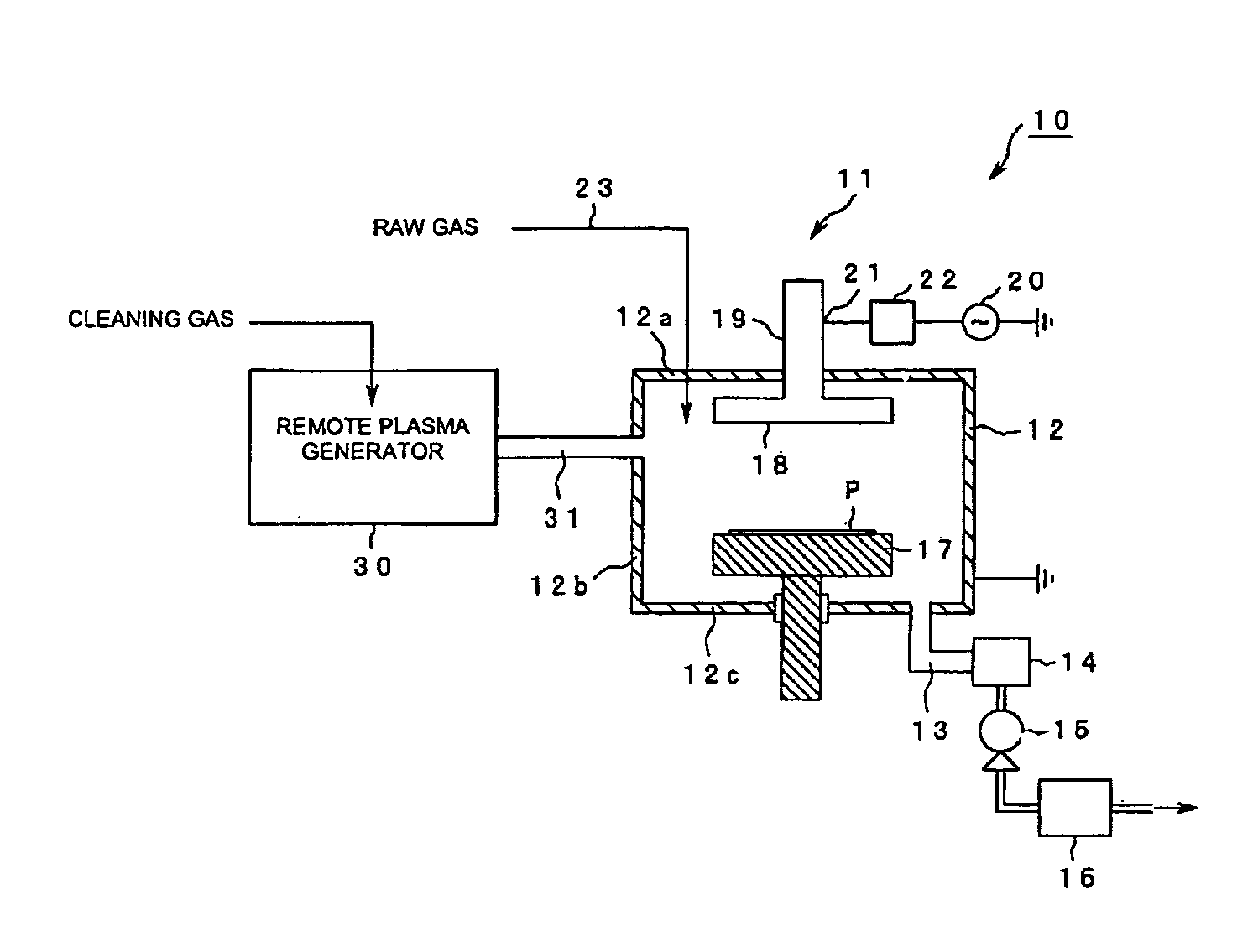
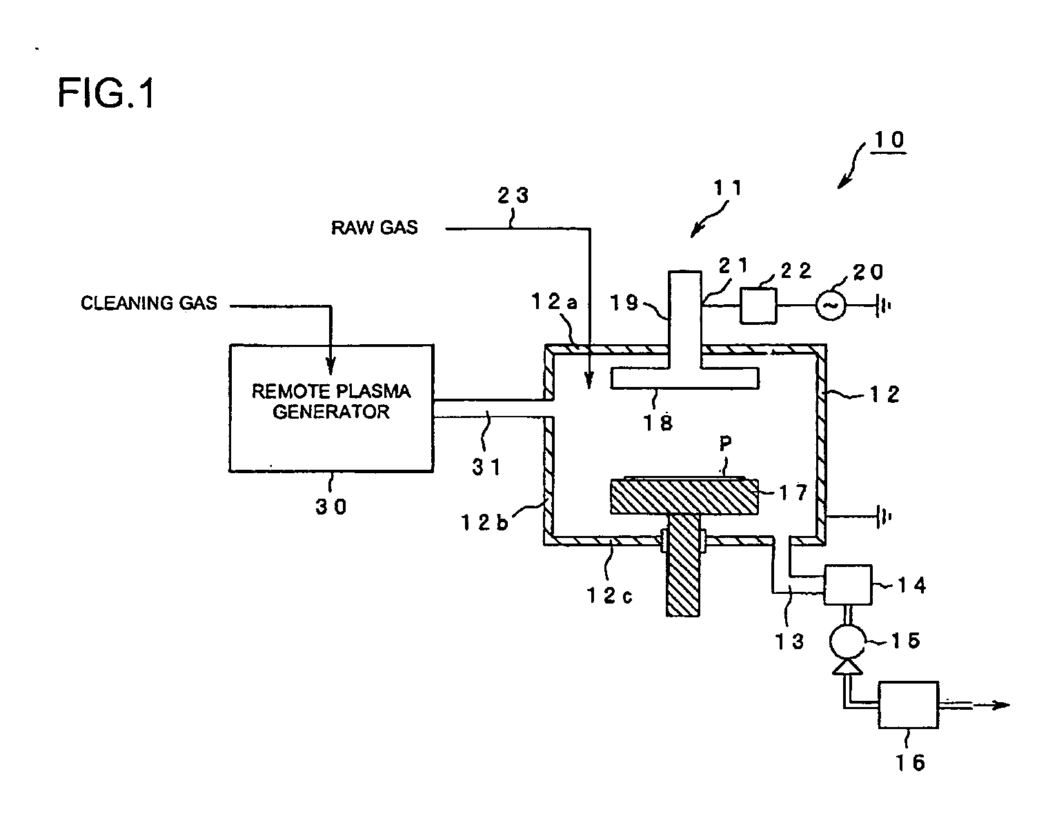
[0032]FIG. 1 is a diagram explaining a cleaning method of a first embodiment of the invention. In the embodiment, the method for cleaning the process chamber of the CVD device will be explained. As for the CVD device, a cleaning device for the plasma CVD device is exemplified.

[0033] As shown in FIG. 1, a cleaning device 10 includes a plasma CVD device 11 and a remote plasma generator 30. The plasma CVD device 11 includes a process chamber 12 kept in vacuum condition (reduce pressure condition), which can be kept at a constant vacuum condition (reduced condition) by exhausting gas from inside the chamber to the outside through an exhaust gas path 13 provided at a bottom wall 12c of the process chamber 12, a high vacuum pump 14, a lower vacuum pump 15, and a detoxification device 16. The detoxification device 16 is the device to turn out the exhausted gas to be harmless and to exhaust it to the outside in an exhausting process before CVD film deposition or after cle...

second embodiment

(Second Embodiment)

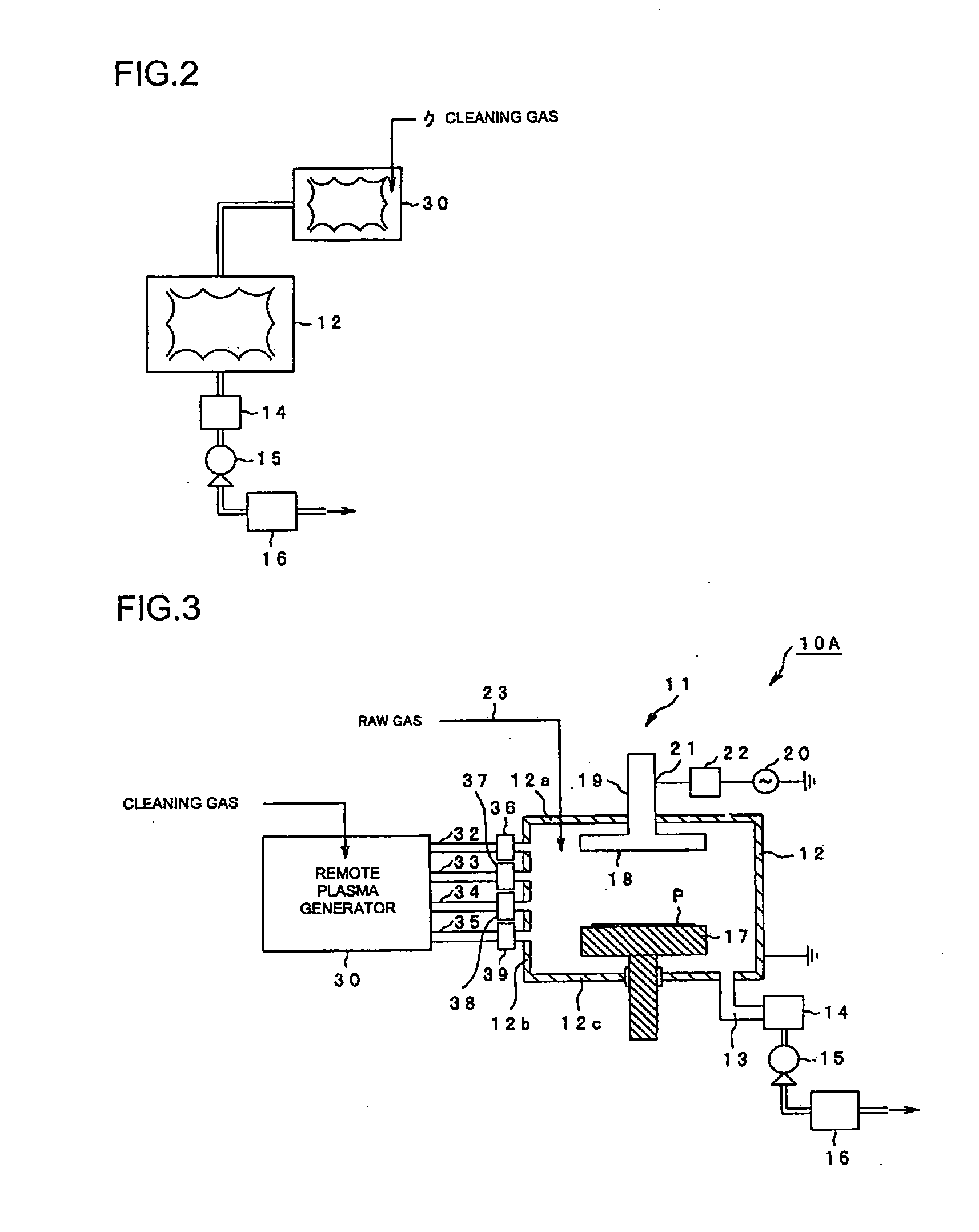
[0052]FIG. 3 is a diagram illustrating a cleaning device to explain a cleaning method of a second embodiment of the invention. In FIG. 2, the same code is given to the part that is same as that in FIG. 1 for explanation.

[0053] In FIG. 3, the cleaning device 10A includes the plasma CVD device 11, the remote plasma generator 30, and a plurality of plasma sources, each of which is correspondingly provided to each of a plurality of pipes that connect the plasma CVD device 11 and the remote plasma generator 30. Specifically, activated gas is led out from the remote plasma generator 30, which is the first plasma source, through a plurality of pipes. In this case, four pipes, namely, pipes 32, 33, 34, and 35 are shown in FIG. 2. The plurality of plasma sources are provided to the pipes correspondingly to be a third plasma source. In this case, four plasma sources, namely, plasma sources 36, 37, 38, and 39 are shown in FIG. 2. Each of the plurality of plasma sources is p...


PUM

PropertyMeasurementUnit
Frequencyaaaaaaaaaa
Vacuumaaaaaaaaaa

Abstract

A method for cleaning a process chamber of a plasma treatment device includes introducing gas that has been activated with a remote plasma source into a process chamber, reactivating the activated gas in the process chamber, reacting the reactivated gas with a deposit inside the process chamber and exhausting the reacted gas.

Description

BACKGROUND OF THE INVENTION [0001] 1. Field of the Invention [0002] The present invention relates to a cleaning method and a cleaning device that removes unwanted Chemical Vapor Deposition (CVD) film accumulated in a process chamber of a plasma treatment device using plasma. [0003] 2. Description of the Related Art [0004] Conventionally, a method for cleaning a CVD device that forms a CVD thin film on a semiconductor substrate is performed by the following manner, for example, in manufacturing of silicon oxide film using a plasma CVD method. A silicon substrate or the like on which a CVD film is deposited is put into a vacuum chamber in which a pair of electrodes whose surface is insulated are provided in parallel, and the temperature is kept constant. After vacuuming inside the chamber, a monosilane and a nitrogen monoxide are flowed. After achievement of a gas flow rate and the pressure at a fixed value, a radio frequency (RF) is applied to the electrodes. Silicon oxide film is gr...

Claims


Application Information

Patent Timeline
IPC IPC(8): B08B7/00C23C16/44H01J37/32H01L21/3065H01L21/31
CPCB08B7/0035Y02C20/30H01J37/32862C23C16/4405Y02P70/50
Inventor SUGIURA, TOSHIKAZU
Owner SEIKO EPSON CORP
Why Eureka
Try Eureka