High speed food product peeling or cleaning machine and method

a cleaning machine and high-speed technology, applied in the field of processing food products, can solve the problems of time-consuming and uncost-effective systems, affecting the quality of food products, and requiring significant maintenance, so as to reduce vibration of rollers, improve throughput and capacity, and increase rotational speed

Inactive Publication Date: 2005-04-21
LYCO MFG
View PDF74 Cites 34 Cited by
  • Summary
  • Abstract
  • Description
  • Claims
  • Application Information

AI Technical Summary

Benefits of technology

[0015] By rotatively supporting each roller adjacent both of its ends, roller vibration is reduced, thereby enabling each roller to be rotated at a higher rotational speed. By doing so, throughput and capacity are advantageously increased. In addition, each roller remains cleaner longer, reducing maintenance.
[0016] Each vibration dampening coupling is

Problems solved by technology

However, knife-type peelers typically have a limited useful life and require significant maintenance in that the knives become blunt in a short amount of time and then need to be replaced.
Clearly, such systems are time consuming and not cost effective, with unacceptable throughput and processing quality.
Such systems provide a one-step peeling process, but suffer in terms of speed and thus throughput.
However, such systems grind large pieces of food product typically down to melon ball or golf ball sizes.
In this system, raw product yield may be cut by 60% or more which typically is unacceptable for root crops that are canned or frozen.
In the past, it was believed that driving abrasive rollers of a bulk food product peeling or cleaning machine at rotational speeds in excess of 500 or 600 revolutions per minute could not be done for extended periods of time required in industrial applications because of issues relating to motor torque constraints, horsepower limitations, reliability, longevity, throughput, quality, and capacity.
For example, while it is believed that the rollers of such peeling and cleaning machines could be driven using a belt drive at these higher speeds, it has not been believed that doing so for extended periods of time would be possible without its reliability suffering and failing prematurely.
It also has been thought too difficult to do so by directly driving each ro

Method used


Image

  • High speed food product peeling or cleaning machine and method
  • High speed food product peeling or cleaning machine and method
  • High speed food product peeling or cleaning machine and method

Examples


Embodiment Construction

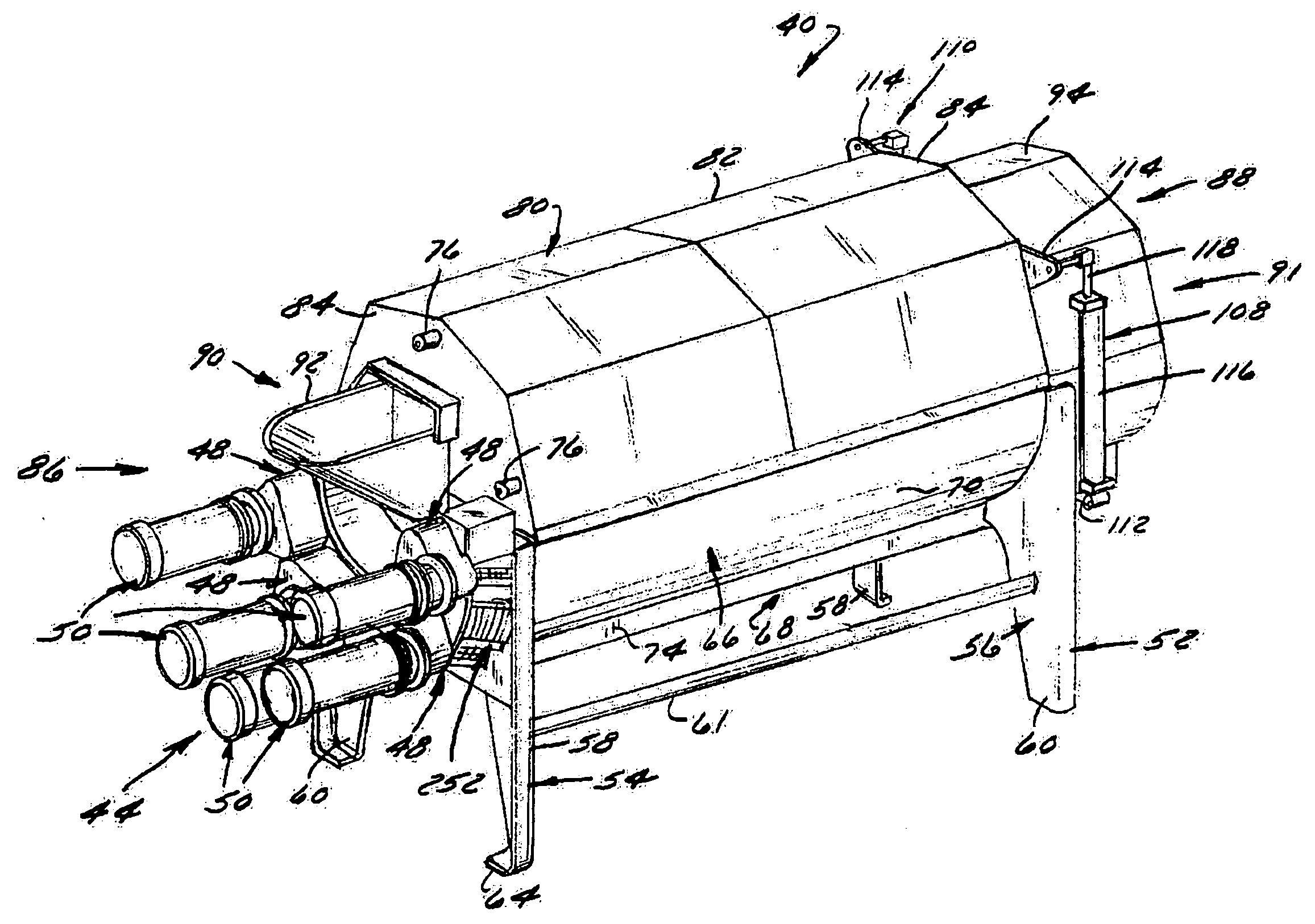
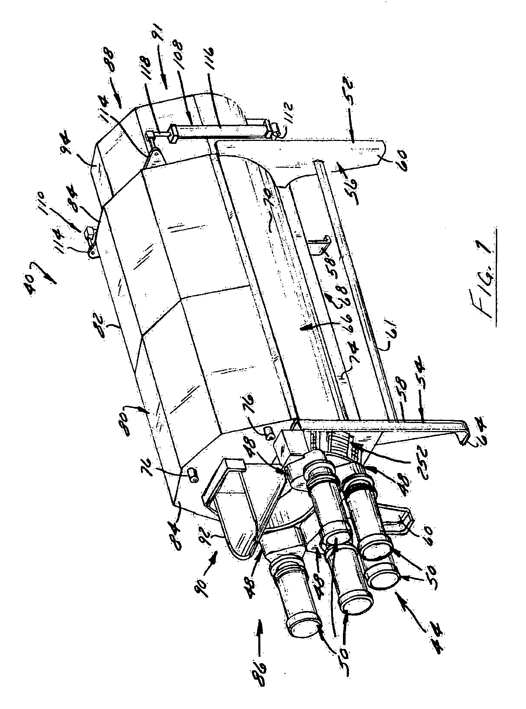
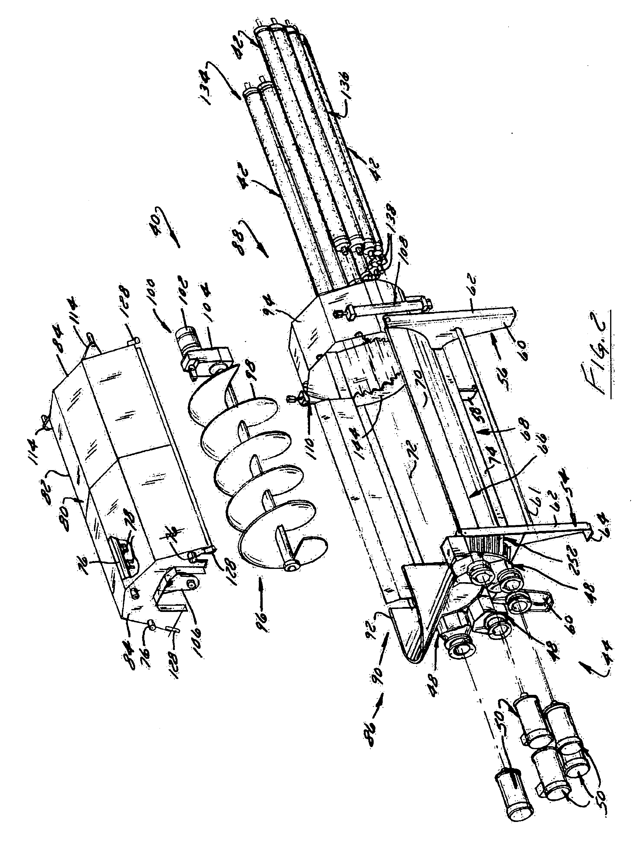
[0049]FIGS. 1 and 2 illustrate a preferred embodiment of a food product processing machine that preferably is a peeling or cleaning machine 40 that includes a plurality of food product processing rollers 42 driven by a drive arrangement 44 such that each roller 42 is rotatable at a rotational speed of greater than six hundred revolutions per minute and preferably seven hundred and fifty revolutions per minute or faster. The drive arrangement 44 preferably includes a vibration damping coupling arrangement 46 (FIGS. 11 and 14) for each roller 42 that helps enable each roller 42 to be rotated at such higher rotational speeds. In a preferred embodiment, the drive arrangement 44 includes a drive box 48 that preferably is a gear box used to transmit motive force to at least one of the rollers 42 from a drive 50.

[0050] The machine 40 includes a frame 52 that has a pair of end plates 54 and 56, each of which includes a pair of spaced apart legs 58 and 60 that support the machine 40 on a su...


PUM


Abstract

An apparatus for peeling or cleaning food product that includes a plurality of rollers each coupled to a drive box, preferably a gear box, by a vibration dampening coupling that preferably is disposed exteriorly of one end of the roller and part of the frame of the machine that supports the roller. A drive that preferably is an electric motor is attached to the drive box such that a plurality of rollers is driven thereby. Such an arrangement enables rollers to be driven at speeds of 600 RPM and preferably 750 RPM or faster, which decreases processing time and increases capacity and throughput. In a method of operation, each roller is driven at a speed of 750 RPM or greater to peel or clean food product before being discharged from the machine. In one preferred method, the rollers are driven at speeds between 900 and 1200 RPM.

Description

CROSS REFERENCE TO RELATED APPLICATION [0001] This application claims priority under 35 U.S.C. Section 119(e) to U.S. Provisional Application Ser. No. 60 / 511,153, filed Oct. 14, 2003, the entirety of which is hereby expressly incorporated herein by reference.FIELD OF THE INVENTION [0002] The present invention is directed to processing food products, and more particularly, to an apparatus and corresponding method of peeling and cleaning food product at high speeds to achieve optimum throughput. BACKGROUND OF THE INVENTION [0003] Machines and corresponding processes for processing food product have taken on many forms. Some such systems can be characterized as knife-type peelers that operate to peel and clean food product in a single step. However, knife-type peelers typically have a limited useful life and require significant maintenance in that the knives become blunt in a short amount of time and then need to be replaced. [0004] In systems that utilize knives in a two-step process,...

Claims


Application Information

Patent Timeline
IPC IPC(8): A23N7/02
CPCA23N12/023A23N7/02
Inventor MAUPIN, DANIEL D.ZITTEL, DAVID R.HUGHES, STEVEN W.
Owner LYCO MFG
Why Eureka
Try Eureka