Calibration and error correction in multi-channel imaging

Active Publication Date: 2005-04-21
ONTO INNOVATION INC
View PDF13 Cites 99 Cited by
  • Summary
  • Abstract
  • Description
  • Claims
  • Application Information

AI Technical Summary

Benefits of technology

[0013] An additional objective of the invention is to provide a means for reducing phase-dependent systematic measurement error of interferometric phase measurements by averaging multiple measurements with random phase offsets of the reference path length.
[0014] In accordance with these objectives, the invention consists of measuring field-dependent geometric distortion for each image produced by the multi-channel system and calculating correction coefficients to remove the distortion from the measurement. According to one aspect of the invention, geometric distortion is determined by projecting a known pattern into the multi-channel imaging system and measuring the position of the pattern in each image with respect to a p

Problems solved by technology

However, even highly corrected real-world optical systems will contain field-dependent image distortion, which may not be perceptible to the human eye but can cause significant measurement errors.
Another problem that can greatly affect the accuracy of multi-channel imaging systems is the non-linear detector response between corresponding image pixels.
This can be caused by electrically dead pixels on the detector array, non-linear electro-optical response, or obscuration due to contaminants such as dust or coating defects within the optical imaging system.
Further, these algorithms reduce spatial resolution.
In addition, prior-art methods for calib

Method used


Image

  • Calibration and error correction in multi-channel imaging
  • Calibration and error correction in multi-channel imaging
  • Calibration and error correction in multi-channel imaging

Examples


Embodiment Construction

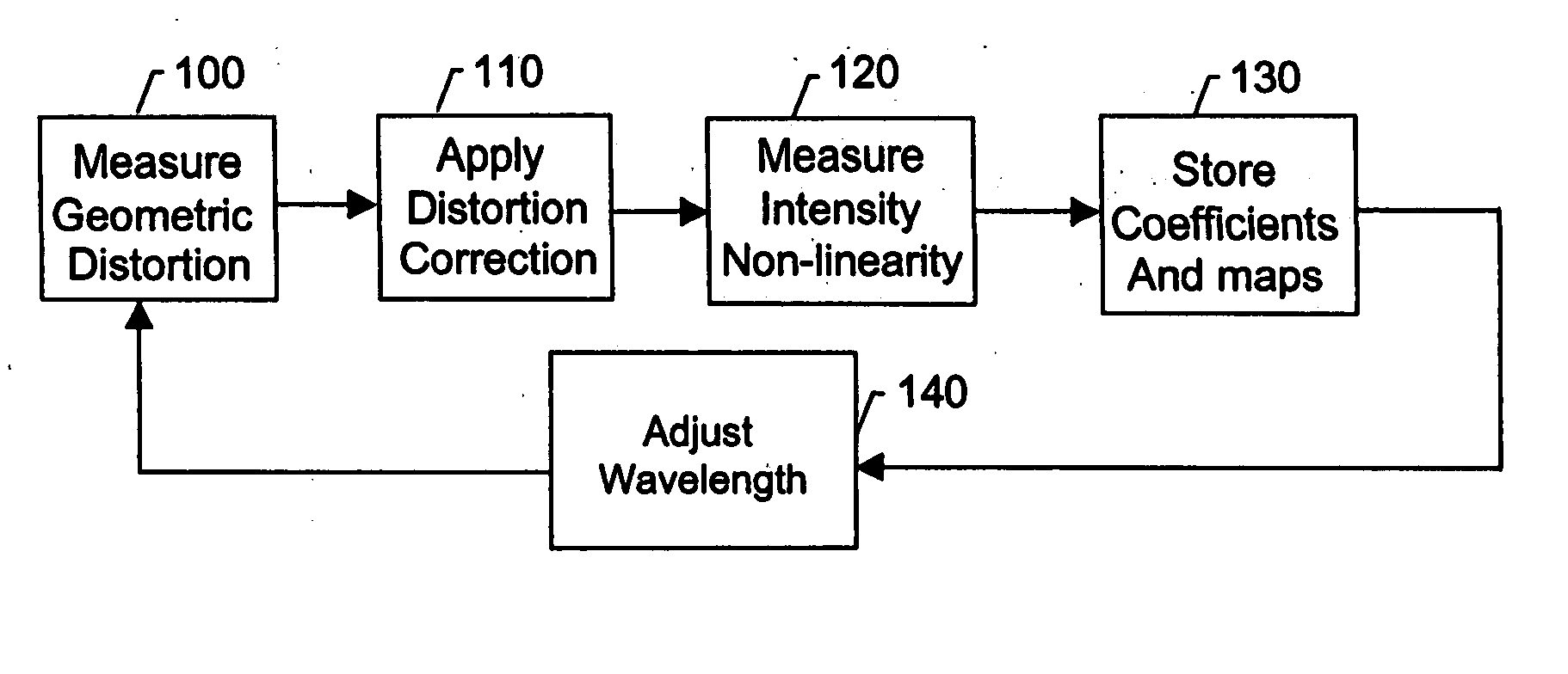
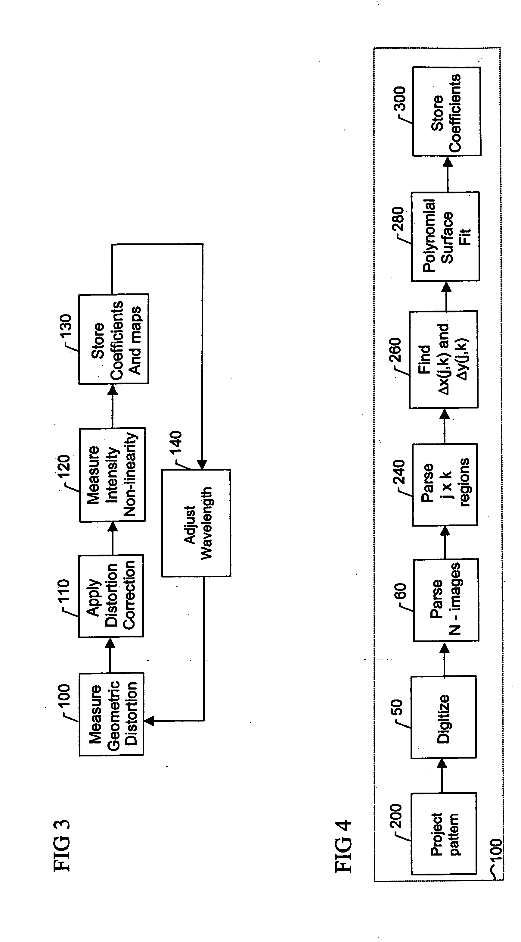
[0029] The present invention provides apparatus and methodology for quantifying and correcting for errors in multi-channel imaging systems. There are three primary types of errors that are addressed in this invention: 1) geometric errors, such as image distortion and registration; 2) deterministic errors, such as channel or pixel dependent attenuation; and 3) stochastic or multivariate errors, such as thermal noise or sensor smear. For the purposes of this disclosure, the term “geometric distortion” is used to refer to those errors that produce distortion and misalignments in the images produced by the multi-channel system. The term “intensity distortion” is used to refer to nonuniformity of intensity detection resulting from attenuation along the optical path, and detector nonlinearity or nonuniformity of response.

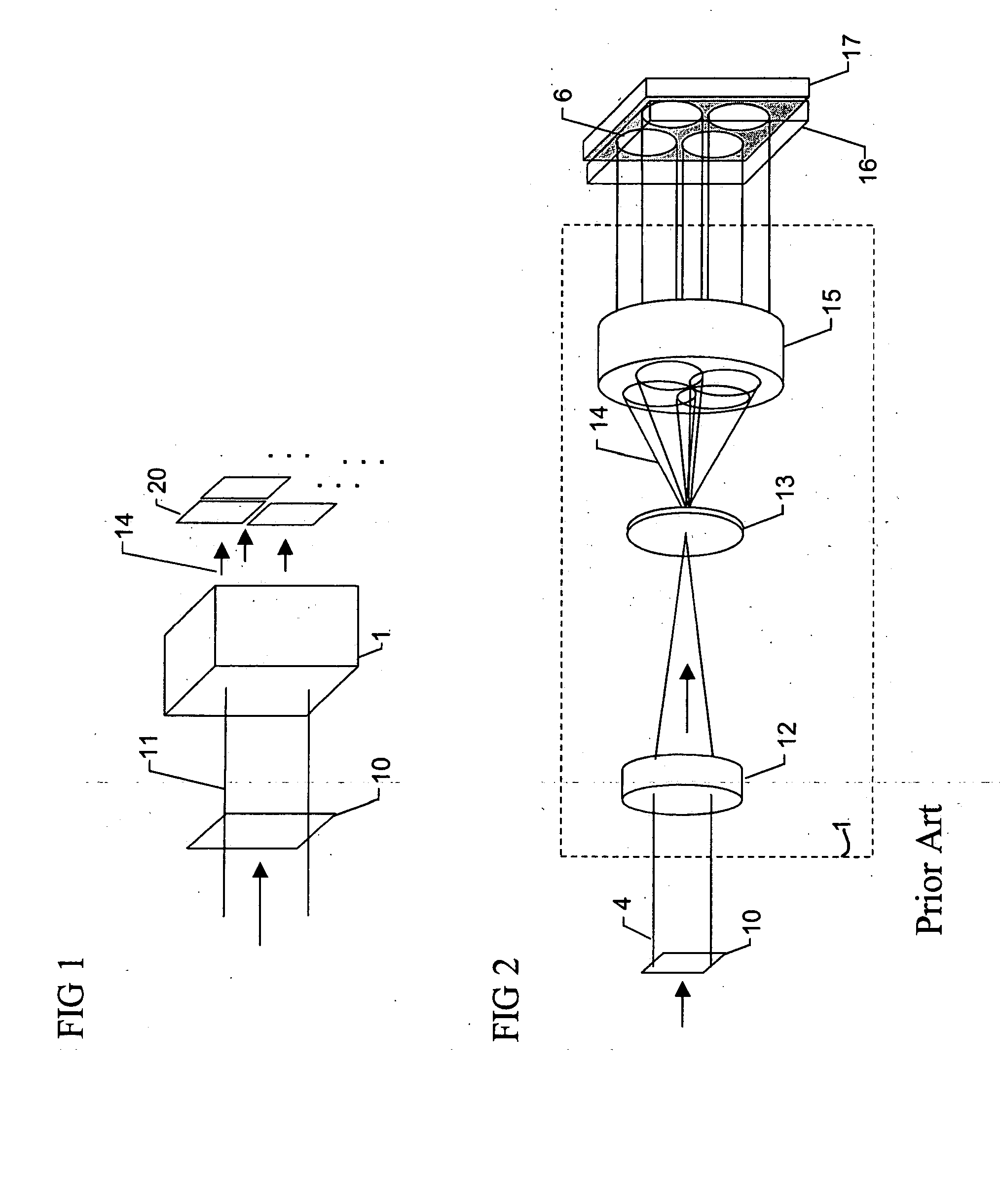
[0030] Turning to the drawings, a generic multi-channel imaging system is shown in FIG. 1. The system consists of an image splitting element 1 that produces a plurality ...


PUM


Abstract

A multi-channel imaging system is calibrated by measuring the geometric distortion in each sub-image, generating corresponding correction factors, and applying such factors to correct subsequent image data. In addition, intensity transfer-function arrays are measured at each pixel, and further used to correct for system and detector nonlinearities and nonuniformity between images. The procedure is repeated over a range of wavelengths to produce a complete set of correction coefficients and transfer functions. When the system is used for interferometric phase measurements, multiple measurements are preferably taken and a random phase offset in the reference path length is introduced at each measurement. The multiple phase data so derived are then averaged to reduce phase-dependent systematic measurement errors.

Description

BACKGROUND OF THE INVENTION [0001] 1. Field of the Invention [0002] The present invention relates to means for calibrating multi-channel imaging systems. In particular, the invention provides an approach for measuring and correcting the field-dependent image distortion, attenuation, and polarization rotation that may be present in multi-channel imaging systems to improve the accuracy of interferometric measurements of optical wavefronts. [0003] 2. Description of the Related Art [0004] Multi-channel imaging systems can be used for the measurement of spectroscopic, polarimetric, and / or interferometric properties of objects by simultaneously acquiring a plurality of images on either single or multiple detector arrays. See, for example, U.S. Pat. No. 5,926,283, No. 5,982,497, No. 4,575,248, No. 5,589,938, No. 5,663,793, No. 5,777,741, No. 5,883,717, No. 4,624,569, and No. 6,304,330. Data from the multiple images can be used for qualitative comparison or can be combined in quantitative w...

Claims


Application Information

Patent Timeline
IPC IPC(8): G01B9/02G01J3/28G01J9/02G06T5/00G06T7/00
CPCG01J3/2803G01J9/02G06T5/006G06T7/0018G06T5/008G01B2290/70G01B9/02083G01B9/02072G01B9/0207G06T7/80
Inventor MILLERD, JAMES E.BROCK, NEAL J.DENNEAU, LARRY JR.
Owner ONTO INNOVATION INC
Why Eureka
Try Eureka