
Analytical test element

a technology of analytical test elements and test elements, applied in the direction of analytical glassware, instruments, and analyses using chemical indicators, can solve the problems of difficult to achieve volumetric metering in these test elements, unfavorable uniformity of transport rate, and blood collection all the more painful for patients, so as to achieve economical and technical simple manufacture, the effect of simple operation

Active Publication Date: 2005-04-21
ROCHE DIAGNOSTICS OPERATIONS INC
View PDF10 Cites 28 Cited by
  • Summary
  • Abstract
  • Description
  • Claims
  • Application Information

AI Technical Summary

Benefits of technology

[0020] Although the present invention is not limited to specific advantages or functionality, it is noted that the present invention provides a self volume-metering test element that is simple to operate, and which enables a spatial separation of the detection area and sample application area using minimal sample volumes. In addition, liquid transport from the sample application and into the detection area is rapid and complete, such that it imposes no limitations on the time required to analyse a sample. For example, in the case of test elements which have several detection elements, the present invention ensures that the liquid sample reaches the individual detection elements as far as possible at the same time and without carry-over problems and, thus, the individual detection reactions can begin as far as possible at the same time. Furthermore, the simple construction of the test element enables an economical and technically simple manufacture.

Problems solved by technology

This type of construction is associated with a number of problems.
When the test strip loaded with sample has to be inserted in an instrument such as a reflection photometer for measurement, potentially infectious sample material can come into contact with parts of the instrument and may contaminate them.
A volumetric metering is often very difficult to achieve in these test elements especially in cases in which the test strips are used by untrained persons, for example, for self-monitoring of blood sugar or coagulation.
In the case that for example blood is used as a sample liquid, blood collection is all the more painful for the patient the more blood has to be collected as the sample liquid.
When using fleeces, papers or membranes for liquid transport, the rate of transport is decisively influenced by the properties of the respective material and hence it is not possible to guarantee uniformly high transport rates.
Furthermore, major disadvantages of the aforementioned materials are that they have a not inconsiderable intrinsic volume and are themselves capillary active due to their microscopic structure.
Consequently, a considerable portion of the originally applied sample liquid is not available for the actual detection of the analyte in such test elements so that larger sample volumes have to be used which in turn have the above-mentioned disadvantages for the patient.
Furthermore, when several detection elements are arranged behind one another on a common test element the problem occurs that the detection reactions do not start uniformly and simultaneously in the detection elements.
In this case the wetting with liquid and thus the start of the detection reaction firstly occurs at the side facing the sample application area so that delays in the start of the detection reaction can also occur within a detection element.
Thus non-uniform and non-reproducible reaction time courses and thus erroneous analyte determinations can occur.
This again puts constraints on the liquid volume to be transported and the transport rate.
Other mechanisms and devices for liquid transport often require the use of active external forces such as pumps thus necessitating additional and hence costly devices.
The channels that have been previously used in test elements often have the disadvantage that they have a not inconsiderable internal volume which, due to capillary activity, retains a portion of the liquid volume to be examined.
Thus, also in such test elements a portion of the originally applied sample liquid is not available for the actual analyte detection.
As a consequence larger sample volumes have to be used which again has the above-mentioned disadvantages for the patients.
However, this has the disadvantage that sharp changes in the surface properties of the two materials can occur at the sites of transition from the wall of the capillary channel to the detection element which can hinder or completely disrupt the transport of liquid.
Hence, it is not possible to guarantee a uniform and simultaneous flow of liquid to be examined to the detection elements.
Instead, the wetting and thus the detection reaction occurs earlier in the area of the detection element that faces the capillary space or the sample application area than in sites that are further removed and, hence, it is not possible to achieve a controlled and uniform detection reaction process and a reproducible determination of the analyte.
Test elements in which capillary active materials such as fleeces or similar materials and, in particular, so-called spreading fleeces or fabrics make the junction between the capillary channel and the detection elements, are subject to similar problems and additionally have the aforementioned disadvantages of fleece-like materials for liquid transport.
A particular disadvantage of this embodiment is that the detection element is a direct component of the channel capable of capillary liquid transport.
As a result, the different surface properties of the individual components of the channel can cause the above-mentioned problems such as impairment or interruption of capillary transport or an irregular wetting of the detection element.
A disadvantage of this is that the very small pore openings of less than 1 μm only allow a very slow penetration of the liquid into the reagent material layer resulting in long measuring times. In particular, when using solutions such as blood which contain particles or cells in high concentrations, the filter membrane can easily become clogged due to the small pore size of the membrane and thus the transport of the liquid to be examined into the detection area can be impaired or interrupted.
Consequently, it is not possible in all cases to ensure that the analyte determination can be carried out and is reproducible.
Another disadvantage is that the analytical device with the sample contained therein has to be heated in order to determine the analyte.
Hence, the use of the analytical device is essentially confined to laboratories.
In this case the sample application area and detection layers are arranged above one another in a vertical axis which results in the aforementioned problems associated with such stack-like arrangements.

Method used


Image

  • Analytical test element
  • Analytical test element
  • Analytical test element

Examples


example 1

Production of an Analytical Test Element (cf. FIG. 4)

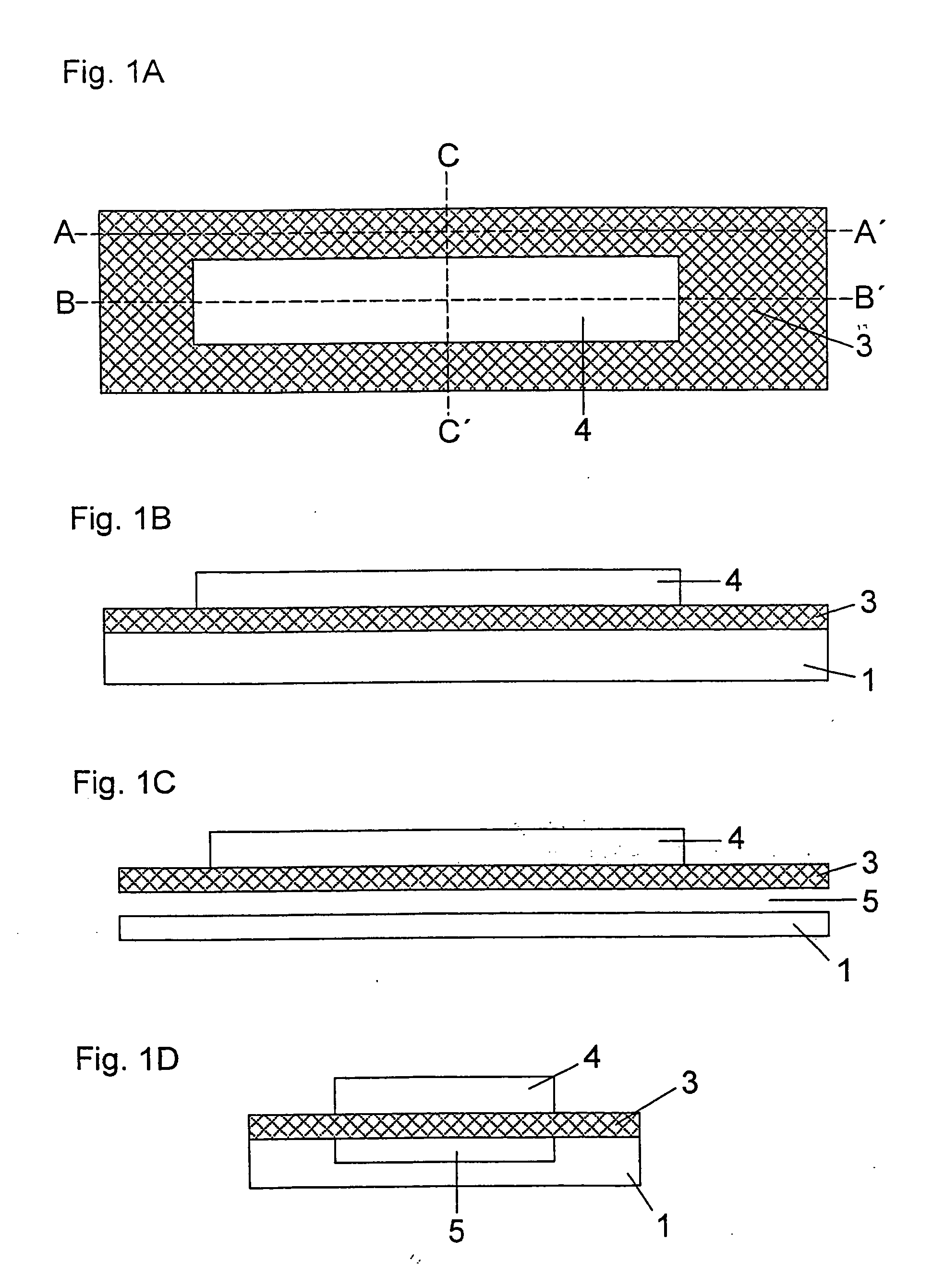
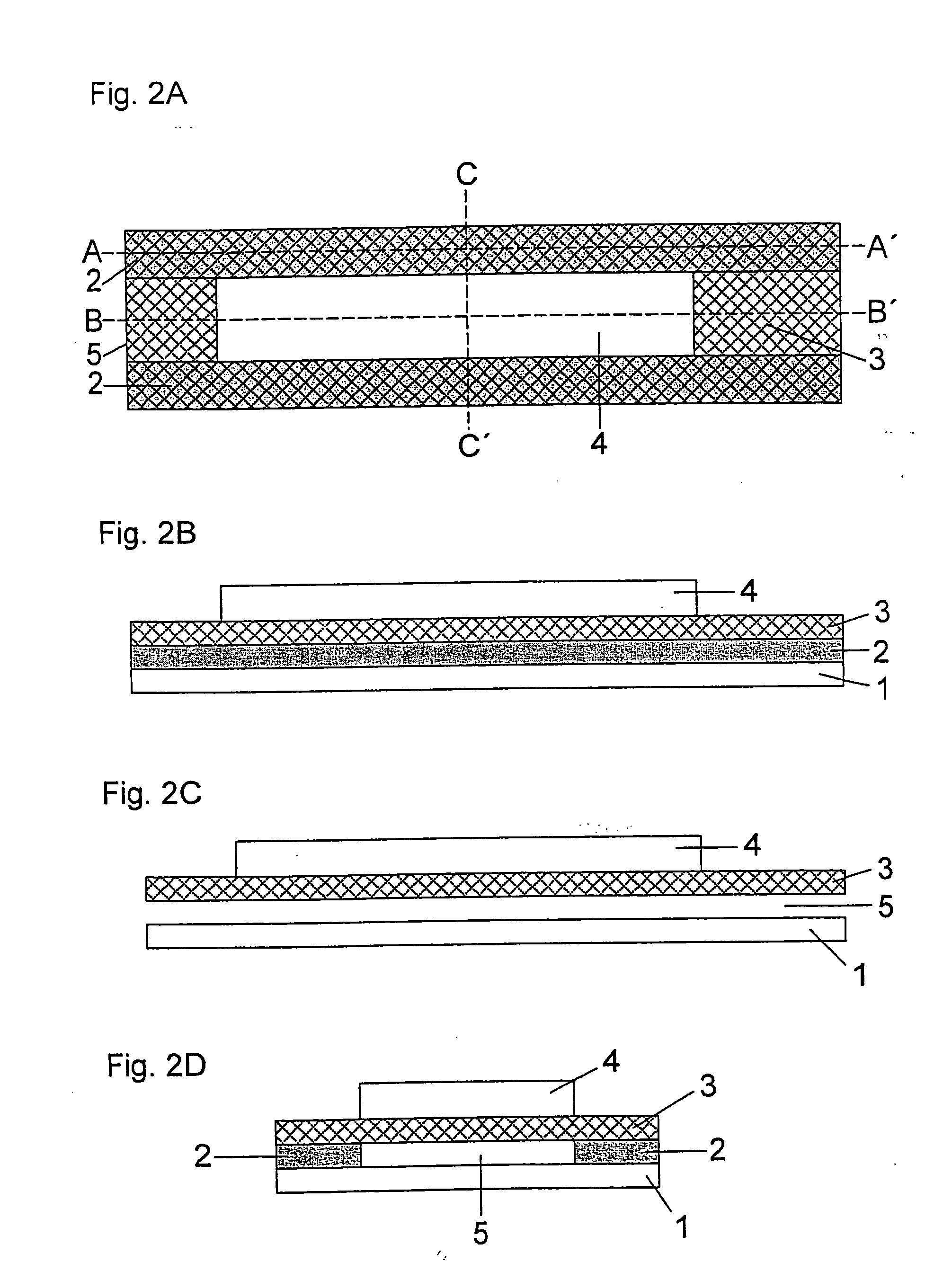
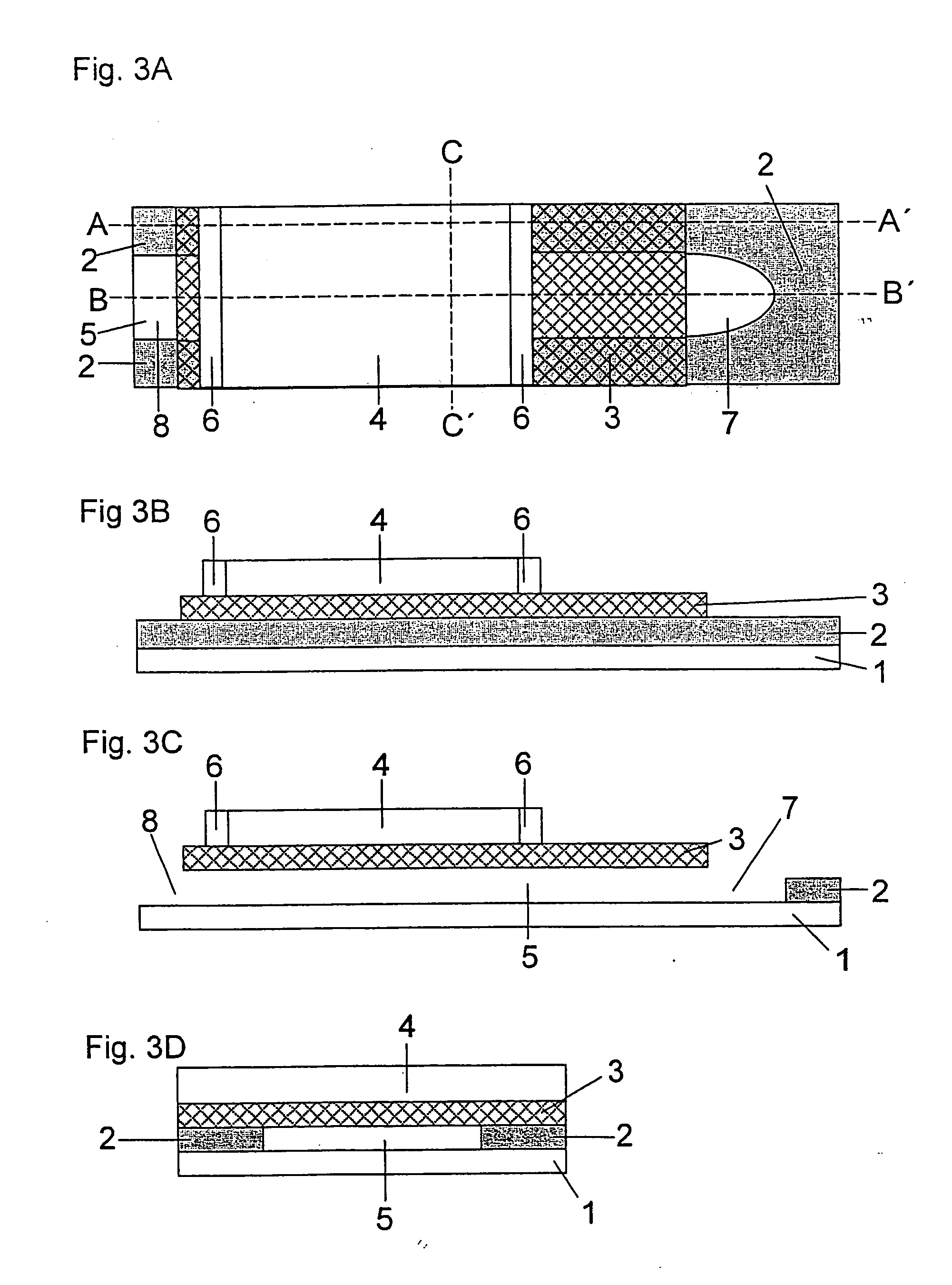
[0097] A double-sided adhesive tape having a thickness of 200 μm is glued a few millimetres from the edge onto a 350 μm thick support foil made of polyethylene terephthalate (Melinex®, ICI, Frankfurt am Main, Germany) which was previously hydrophilized by treatment with dioctyl sodium sulfosuccinate (2% in ethanol, Merck KgaA, Darmstadt, Germany). The support foil has a length of 75 mm and a width of 5 mm. The adhesive tape has a length of 35 mm and also a width of 5 mm. In addition, one end of the adhesive tape which corresponds to the subsequent vent hole has a central punched hole of 2 mm width and 15 mm to 25 mm length which defines the dimensions of the capillary channel. A specially shaped sample application area typically adjoins the side of the punched hole opposite to the vent hole. This is formed by an oval punched hole of 6 mm length and 3 mm width. The length of the punched hole can be selected to be slightly larger t...

example 2

Measurement of Lipid Parameters with the Aid of the Test Element From Example 1

[0098] The sample application area of the test element from Example 1 is contacted with one drop of blood. The capillary of the test element automatically and uniformly fills with sample liquid within 3-5 seconds. In the areas of the detection elements the sample liquid flows across the network essentially simultaneously into the detection elements which starts the respective detection reaction. A colour development in the detection element is visible within a few seconds which can be used after completion of the measuring time to determine the analyte. This measuring time is, for example, about 135 sec. for a HDL cholesterol determination according to the Reflotron® HDL cholesterol method, about 135 sec. for a cholesterol determination according to the Reflotron® cholesterol method, and about 180 sec. for a triglyceride determination according to the Reflotron® triglyceride method. The intensity of the ...


PUM


Abstract

An analytical test element for determining at least one analyte in a liquid is provided comprising a support, at least one detection element, and a channel capable of capillary liquid transport which is at least partially formed by a hydrophilic network, one side of which is at least partially in contact with the inner space of the channel and the opposite side of which is at least partially in contact with the detection element such that liquid can be transported from the channel across the network to the detection element. The invention also concerns the use of the analytical test element to determine an analyte in a liquid and a method for determining at least one analyte in the liquid with the aid of an analytical test element.

Description

BACKGROUND OF THE INVENTION [0001] The present invention concerns an analytical test element for determining at least one analyte in a liquid, the use of an analytical test element according to the invention to determine an analyte in a liquid and methods for determining at least one analyte in a liquid with the aid of an analytical test element according to the invention. [0002] So-called carrier-bound tests are often used for the qualitative and quantitative analytical determination of components of liquids and especially of body fluids such as blood. In these tests, reagents and, in particular, specific detection reagents and auxiliary reagents, are embedded or immobilized in suitable layers of a solid support. These layers are referred to as detection elements. In order to determine the corresponding analyte the liquid sample is brought into contact with these detection elements. If a target analyte is present, the reaction of liquid sample and reagents usually results in a sign...

Claims


Application Information

Patent Timeline
IPC IPC(8): G01N33/52B01L3/00G01N31/22G01N33/48G01N33/80G01N33/92G01N35/10
CPCB01L3/5023B01L3/5027B01L2300/087Y10T436/255G01N33/80G01N33/92G01N31/22
Inventor BRAUNER, MICHAEL
Owner ROCHE DIAGNOSTICS OPERATIONS INC
Learn More