Fluid exchange system for controlled and localized irrigation and aspiration

a fluid exchange system and fluid flow technology, applied in the direction of catheters, infusion syringes, surgery, etc., can solve the problems of embolism, embolism danger, and inability to prevent embolism, so as to promote the removal of debris within the vessel, improve the fluid exchange and fluid flow parameters, and enhance the effect of removal of embolism

Inactive Publication Date: 2005-04-21
FOX HOLLOW TECH
View PDF8 Cites 235 Cited by
  • Summary
  • Abstract
  • Description
  • Claims
  • Application Information

AI Technical Summary

Benefits of technology

[0043] As noted above, an advantage of the invention is the generation of localized turbulence in the vicinity of the infusion catheter such that volume exchange or fluid circulation within the vessel promotes the removal of debris within a vessel and the disruption of embolic particles that are only loosely attached to the interior walls of a vessel. This advantage is derived from both the design of the distal end of the catheter, including the number, orientation, and dimensions of irrigation ports, this also affects the relative location in which fluids are inserted and removed into a vessel or an organ, as well as the specific design and function of the fluid exchange apparatus that, when coupled with the catheter of the invention, combine to produce improved fluid exchange and fluid flow parameters. For example, in an ordinary vessel that is roughly cylindrical within a defined axial distance along the length of a vessel, the mere removal of liquid through simple aspiration with a conventional apparatus generally produces a laminar flow through the center of the annular structure of the vessel and the fluid along the walls of the vessel are largely left in place. With a turbulent fluid flow profile, the fluid introduced into the vessel causes an exchange between the irrigant and the existing fluid that is localized along the vessel walls, and generally causes a more thorough mixing of the fluids within the vessel such that a more complete fluid volume exchange occurs and the removal of embolic particles is enhanced.
[0044] Although the particular parameters vary according to the designs described below, the fluid exchange and fluid circulation achieved by the apparatus of the invention results in an insertion and removal of a volume of fluid from within a treatment site within a body conduit. As described in further detail below, the overall system is comprised of a fluid exchange apparatus that may have a mechanical or electrical (or both) fluid exchange component that converts a defined volume of fluid exchange with a defined axial movement of the catheter such that the volume of fluid exchanged per measure of distance of axial movement of the catheter through a vessel is known. Preferred embodiments of the fluid exchange apparatus are a substantially closed system wherein a reservoir containing irrigating fluid is combined with a reservoir containing the aspirated fluid. This invention provides several embodiments wherein known volumes are exchanged through a system that is essentially “closed” except for the exchange site within the vessel. The terms “substantially closed” mean that the system is closed because the volume of fluid inserted as irrigant solution is removed as aspirant solution in a predetermined ratio and any deviance from the ratio is attributed to only a volume of solution that is retained within the body at the target exchange site.
[0045] For example, when a system of the invention is applied to irrigate and aspirate fluid from within a vessel, the system is substantially closed because the only difference between the fluid inserted as irrigant and removed as aspirant is that which is purposefully left behind in the vessel. When the volume exchange ratio of the device is set at a 1:1 ratio, the volumetric exchange of fluids is very near to equivalent. The fluid exchange apparatus may also be actuated in such a manner that the flow produced by actuating the fluid exchange apparatus is a defined increment. Thus, a known volume of fluid is exchanged at the target site and the clinician knows with certainty the volume of irrigant fluid that is inserted as well as the volume of fluid that is aspirated out of the target site.
[0046] In one embodiment of this aspect of the invention, the fluid is recirculated within the irrigation and aspiration lumens and associated fluid conduits of the apparatus of the invention. As described in more detail below, fluid flow can be reversed in either the irrigation or aspiration lumen to provide for fluid recirculation through the target site. In this embodiment, a defined volume of fluid that is contained, in at least a portion of the catheter device, is moved in two directions within the irrigation or aspiration lumen to recirculate a defined quantity of liquid. Thus, a portion of fluid present in the irrigation lumen is introduced to the treatment site and withdrawn through the aspiration lumen, through manipulation of the fluid conduits that are external to the catheter device, the fluid flow is reversed such that the defined volume of fluid originally present in the irrigation lumen, and having passed through the treatment site and into the aspiration lumen, is reversed. This defined volume of fluid passes through the treatment site for at least a second time and may re-enter the irrigation lumen.
[0047] As noted above, and in the pertinent example that follows, this embodiment is particularly useful for high value pharmaceutical products where concentrated exposure in the therapeutic site is valuable. For example, enzymes and other therapeutic compounds that alleviate a blockage or lesion within a treatment site, such as urokinase, tissue plasminogen activators, and other such compounds, can be concentrated and continually recircled throughout a treatment site without performing quantitative volume exchange as described elsewhere herein. To enable such a system, several embodiments are possible wherein the catheter is manufactured to provide for the capability to install a closed loop to recirculate fluid. Advantageously, a simple valve system can be added to the catheter embodiment at a point external to the catheter through simple connections to the irrigation and aspiration lumen. The structural details and operation of this embodiment are described in further detail below.
[0048] In another embodiment, the device of the invention provides a 1:1 ratio of irrigation to aspiration fluid exchange such that the volume of fluid introduced to a vessel or organ is exactly matched by the volume removed. Through control of the location and movement of the device of the invention, the interior of a vessel or organ can undergo a complete fluid exchange by advancing the infusion catheter along the length of a vessel where removal of fluid is desired. By this process, several results are achieved that are beneficial therapeutically. First, as noted above, the vessel experiences a turbulence and a fluid flow that is physiologically relevant in the sense that both the volume of fluid moving across a vessel as well as the turbulence are similar to the parameters that the vessel would experience under blood pressure. This similarity has several aspects. First, the turbulence that occurs in a vessel is similar to the turbulence caused by the motion of blood moved by a beating heart. Second, the pulsatile nature of the fluid exchange is also similar to the varying pressures and pressure profile caused by ventricular contraction and the ordinary movement of blood throughout the arterial system. Finally, these specific fluid flow characteristics are achieved without producing substantially increased pressures within a vessel and without distending the vessel through the application of increased fluid pressures. Thus, the combined irrigation and aspiration of controlled volumes of liquid treat the vessel with a physiologically relevant fluid profile.

Problems solved by technology

Catheter-based irrigation and aspiration systems are unique in many respects due to their use in clinical situations where blockages or lesions exist inside a blood vessel, such as a coronary or carotid artery, and dangers arise from the creation and release of tiny particles of debris called “emboli” within the vessel.
In many intravessel therapeutic procedures, the danger from the creation of emboli is an unavoidable aspect of the therapeutic procedure whenever a catheter is introduced to a target site.
However, while each of these procedures offers therapeutic value in treating the lesion, each carries the risk of creating emboli during the procedure.
In addition to the creation of emboli, there exists the risk of microemboli, thrombotic or otherwise in nature, which can cause substantial blockage of the microvasculature and microcirculation resulting slow flow or no reflow phenomena.
In some cases, the basic performance of the procedure inherently creates emboli, whereas in other procedures, the manipulation of the vessel and the insertion or removal of a therapeutic or diagnostic catheter is the cause of emboli generation.
As with any procedure conducted in the cardiovascular system, the risk is particularly great where emboli created from plaque dislodged from inside a blood vessel travel to the brain and cause serious brain injury or death.
For example, treating lesions of the carotid vessels in the neck necessarily involves high risk because any emboli that are created travel immediately to the brain.
Unfortunately, the process of moving a distal device through a clogged vessel and across a carotid lesion can generate emboli that lead to a cerebral ischemia or stroke.
Moreover, studies have shown that crossing a carotid lesion with a structure as small as a catheter guide wire can generate emboli.
Also, some lesions carry such a high risk of generating emboli that therapeutic treatments are attempted only in the most severe cases.
Where a chronic total occlusion (an untreatable total blockage) exists, the diagnosis is particularly poor because it is impossible for medical personnel to place a structure beyond the point, or “distal” of the occlusion, such that emboli generated by the removal of the occlusion can be captured before entering the circulation of the bloodstream.
Such chronic total occlusions can only be treated by removing the occlusion from the “proximal” side, where emboli removal is uniquely difficult.
Thus, even when a filter is used as an added safety feature, such systems cannot protect the patient against the potential harm inherent in the placing the device itself.
This carries the risk that the filter will impact the vessel and cause the release of emboli and / or contact the stent and either displace the stent or similarly cause the release of embolic particles at the end of the procedure.
However, the tissue of the inside walls of a vessel that is affected by a lesion is notoriously delicate and the treatment of the lesion has the capability to generate or release emboli whenever any mechanical manipulation of the portion of the vessel containing the lesion occurs.
Filters also have inherent drawbacks that cannot be completely eliminated.
Also, particles larger than the pore size tend to become trapped in the filter such that the filter itself becomes an occlusive element and blood flow through the filter is impeded.
Disadvantages of a two-balloon system also arise from the placement of balloons on both sides of a lesion and the nature of the blood flow that occurs in the region of the vessel containing the lesion once the balloon is removed.
This results from the disruption in the haemodynamics of the flow in the vessel due to the restriction caused by the lesion, resulting in further disease downstream.
Thus, the use of any occluding member distal of a lesion does not eliminate the risk of creating emboli that may enter the vessel.
The risk is particularly great when a second balloon is used because the balloon is not advantageously placed for the removal of emboli created by the use of the balloon itself and because the balloon must be removed by passing it across the lesion upon completion of a procedure.
This drawback is present in all circumstances when a balloon is advanced across a lesion because, when any occluding member is placed distally of the lesion, the occluding member must be drawn back across the lesion to remove the occluding member at the end of a procedure.
Also, the placement of two balloons requires additional time to inflate the second balloon and adds to the complexity of a device due to an additional lumen that must be incorporated into the catheter to inflate the balloon.
Because the second balloon is relied upon to prevent the flow of emboli past the region of the vessel containing the lesion, the failure of the balloon is a critical event that threatens the health of a patient undergoing the procedure.
Furthermore, due to geometric constraints, the second balloon often acts as the guide wire as well.
When delivering tools to perform the therapeutic or diagnostic procedure within the vessel, the balloon may move and disrupt the vessel wall or compromise the retrieval of emboli.
Introduction of tools and other manipulations of a distally located balloon can also result in deflating the balloon or otherwise causing the balloon to lose patency on the interior of the vessel.
Anytime that a balloon is placed distal to a lesion, the contact between the balloon and the lesion carries the risk of damaging the vessel.
For example, to make the seal tight enough to prevent the passage of fluid and emboli past the balloon, the expansion of the balloon typically deforms the vessel outward and may disrupt plaque in and about the point of contact between the vessel and the balloon.
Moreover, any plaque that becomes dislodged outside the barrier formed by the balloon is released into the blood stream because there is no mechanism distal of the balloon to remove the emboli.
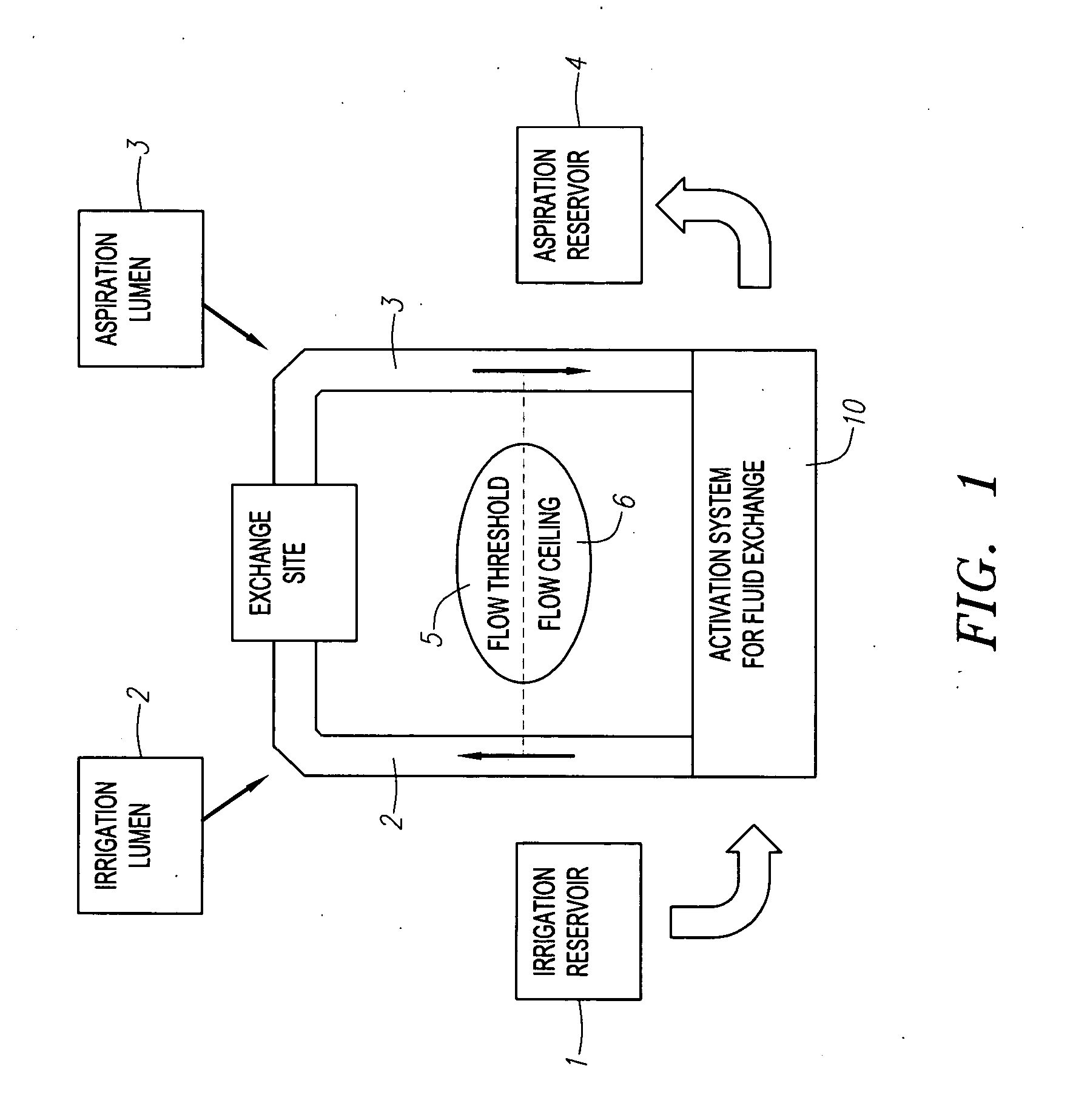
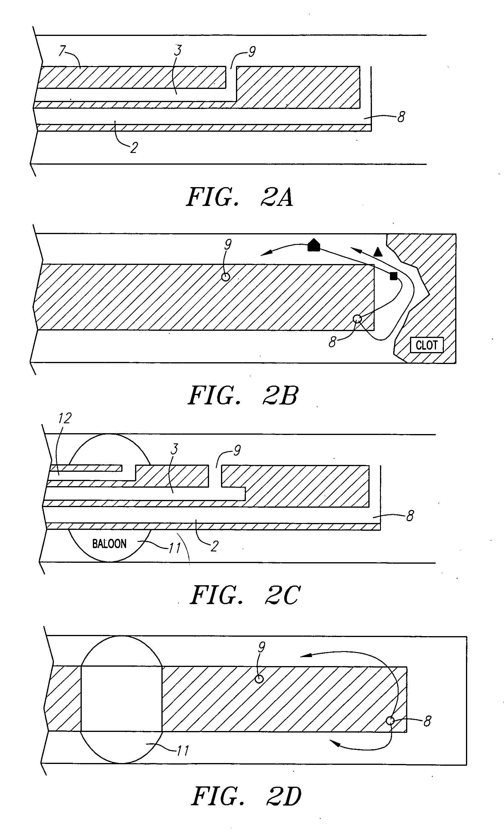
For example, removal of fluid and / or embolic particles by simple suction from within a body conduit may only remove a portion of the fluid present in the vessel and may leave emboli in place even if all of the fluid is removed and replaced.
Thus, a system that provides limited fluid exchange is particularly unlikely to achieve a complete removal of emboli.
Also, given that the interior walls of a vessel may have been contacted from within during a therapeutic procedure, a high likelihood exists that additional particles may be dislodged upon the establishment of a robust fluid flow through the vessel.
Under these circumstances, an even greater risk exists that plaques located downstream from the lesion will be dislodged and will enter the circulation causing serious injury.
A common feature of these structures that need medical intervention is a protected environment in which infectious pathogens can harbor and grow, can accumulate collections of toxic, pro-inflammatory and / or necrotic materials, can expand and cause mechanical interference, and can affect the proper functioning of their resident or neighboring tissues.
Abscesses that rupture can lead to recurrent infections or septic shock.
Cysts can rupture, leading to hemorrhage, pain or irritation.
Pleural effusions can limit the ventilation capacity of lungs.
However, the longer the catheters are left in place, the more time there is for an infection to occur as a result of catheter insertion.
Pseudocysts can become very large and compartmentalized, can encroach on neighboring structures and can cause mechanical interference with proper function.

Method used


Image

  • Fluid exchange system for controlled and localized irrigation and aspiration
  • Fluid exchange system for controlled and localized irrigation and aspiration
  • Fluid exchange system for controlled and localized irrigation and aspiration

Examples


Embodiment Construction

[0146] The present invention may be used in a number of different environments and for a variety of purposes including, but not limited to all physiological uses of peristaltic or other pump for aspiration and irrigation including, IVUS, OCT, angioplasty, endarterectomy, cardiac stent placement, vessel treatment, diagnosis and repair, surgical placement of non-cardiac stents, insertion of pig-tail catheters, ear rinsers, etc. The following detailed description is exemplary of possible embodiments of the invention.

[0147] Referring to FIG. 1, a schematic representation of the invention shows the basic components of the device necessary for implementation. The core fluid exchange or activation system maintains a substantially closed loop system with the target site for fluid exchange, e.g. the site within the body where aspiration and irrigation are applied. The irrigation component of the invention is conveniently provided by a dedicated irrigation reservoir 1, particularly when the ...


PUM


Abstract

The control of fluid introduction into and out of body conduits such as vessels, is of great concern in medicine. As the development of more particular treatments to vessels and organs continues it is apparent that controlled introduction and removal of fluids is necessary. Fluid delivery and removal from such sites, usually referred to as irrigation and aspiration, using fluid exchange devices that control also need to be considerate of potential volume and / or pressure in the vessel or organ are described together with catheter and lumen configurations to achieve the fluid exchange. The devices include several electrically or mechanically controlled embodiments and produce both controlled and localized flow with defined volume exchange ratios for fluid management. The applications in medicine include diagnostic, therapeutic, imaging, and uses for the introduction or removal of concentrations of emboli within body cavities.

Description

CROSS-REFERENCE TO OTHER APPLICATIONS [0001] This application is a continuation-in-part of U.S. Provisional Patent Application Ser. No. 60 / 306,315, filed Jul. 17, 2001, and regular U.S. utility application Ser. No. 10 / 198,718, filed Jul. 17, 2002.FIELD OF THE INVENTION [0002] The devices and related methods of the invention relate to the controlled introduction and removal of fluids in diagnostic, therapeutic and imaging applications within the body. Specifically, the invention relates to the advantageous use of a fluid exchange device in combination with a specially designed catheter to produce a system for controlled aspiration and irrigation. The systems of the invention also include fluid circuits that enhance the ability of a user to achieve selective and localized exchange of fluids within a body conduit, for example, in the diseased region of a blood vessel having a blockage or lesion. The devices of the invention, and the methods enabled by the use of the devices, have sever...

Claims


Application Information

Patent Timeline
Patent Type & Authority Applications(United States)
IPC IPC(8): A61M1/00A61M3/00A61M5/315A61M25/00
CPCA61M1/0009A61M1/0058A61M1/0064A61M1/0068A61M25/0075A61M2005/3152A61M25/007A61M1/67A61M1/774A61M1/81
Inventor MACMAHON, JOHN M.GOFF, THOMAS G.COURTNEY, BRIAN K.
Owner FOX HOLLOW TECH
Why Eureka
Try Eureka