

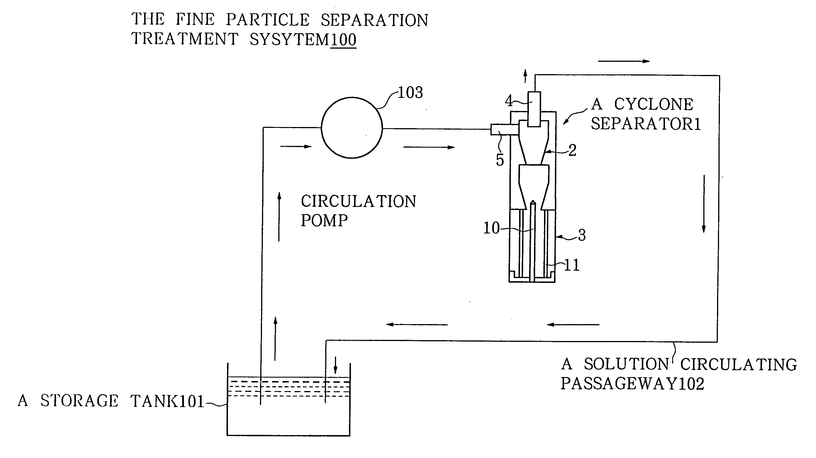
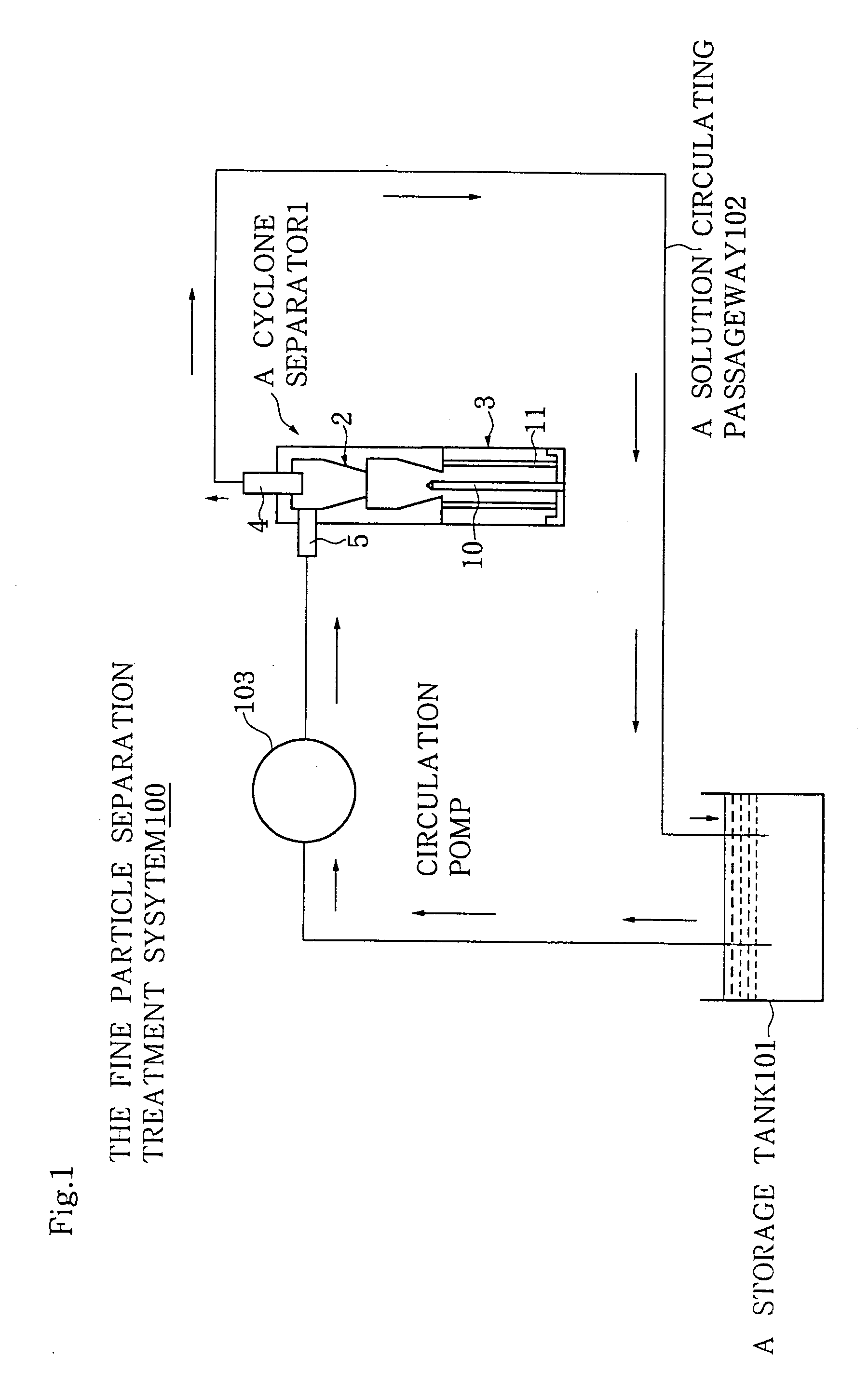
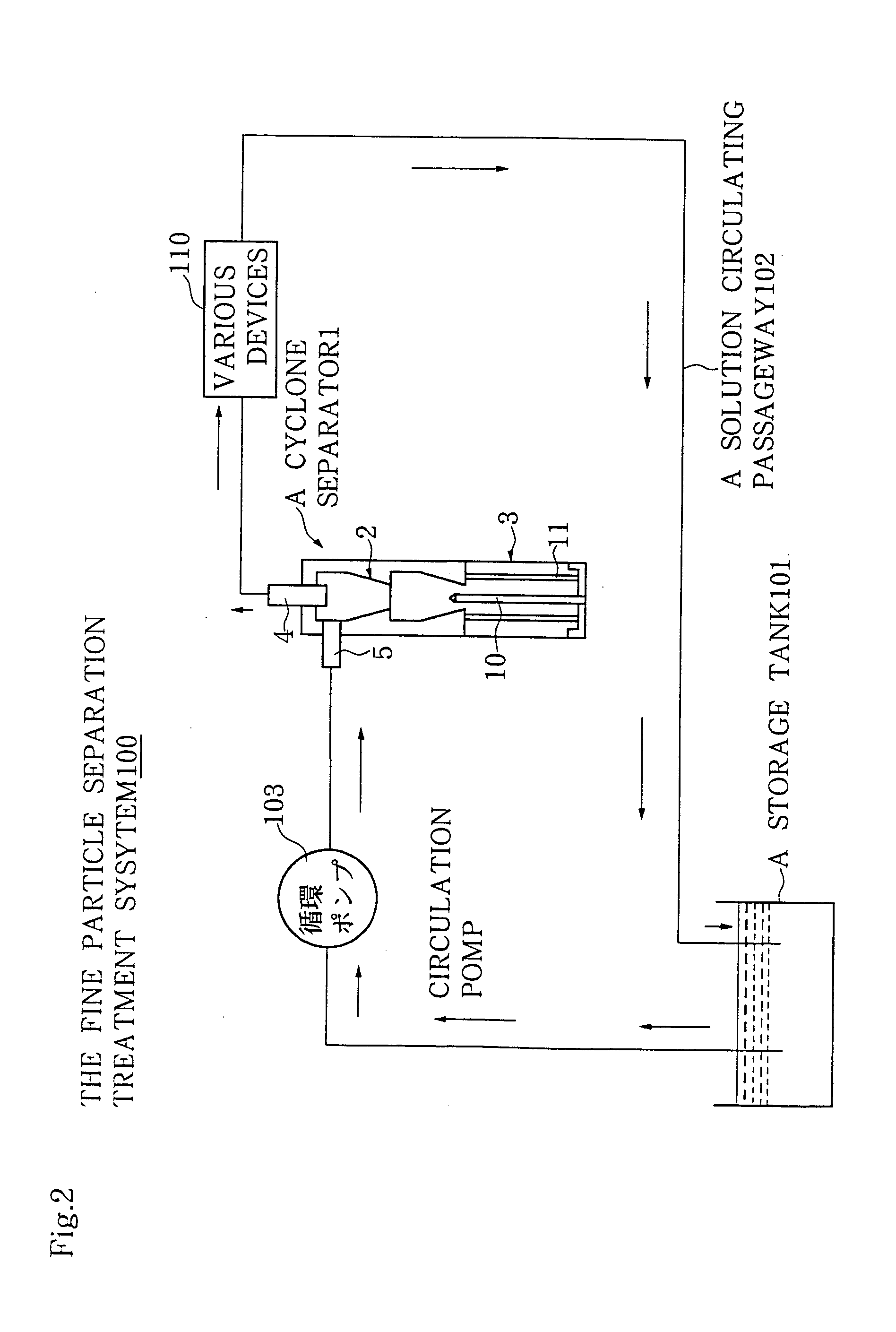
Fine particle separation treatment system and cyclone separator
a technology of treatment system and cyclone separator, which is applied in the direction of filtration separation, multi-stage water/sewage treatment, separation process, etc., can solve the problems of increasing processing cost, complex system structure, and achieving the desired purity of fine particles and cutting liquid
- Summary
- Abstract
- Description
- Claims
- Application Information
AI Technical Summary
Benefits of technology
Problems solved by technology
Method used
Image

Examples
example
[0049] Adhesion of silica particles was tested using: the cyclone separator (FIG. 7A) having no electrodes as shown in FIGS. 3 and 4; the cyclone separator (FIG. 7B) as shown in FIGS. 1 and 2; the cyclone separator (FIG. 7C) as shown in FIG. 5; and the cyclone separator (FIG. 7D) as shown in FIG. 6. A dispersion solution of silica particles in ion-exchange water was used as a sample.
[0050] The results of measurements are shown in FIGS. 8 and 9. Compositions of crude powders (silica powder before separation with the cyclone separator) and separated fine powders relative to the proportion of silicon (Si: 100%) in a silicon dioxide powder as a starting material are shown in FIG. 8, wherein the powders were subjected to separation treatments using the cyclone separator having (a) no electrode as shown in FIG. 7A, (b) the standard electrode shown in FIG. 7B with an applied voltage of 50 V, (c) the elongated electrode shown in FIG. 7C with an applied voltage of 50 V, and (d) the conical ...
PUM
| Property | Measurement | Unit |
|---|---|---|
| applied voltage | aaaaa | aaaaa |
| flow rate | aaaaa | aaaaa |
| electric charge | aaaaa | aaaaa |
Abstract
Description
Claims
Application Information