Optical detection and analysis of particles

a particle and optical detection technology, applied in the field of optical detection and analysis, can solve the problems of limited monitoring ability, insufficient amount of energy coupled through the metal from the incident illuminating beam to the evanescent surface plasmon field, and the limited ability of the bacterial cell to be visualised by this technique, etc., to achieve the effect of enhancing performan

Active Publication Date: 2005-10-13
MALVERN INSTRUMENTS
View PDF2 Cites 28 Cited by
  • Summary
  • Abstract
  • Description
  • Claims
  • Application Information

AI Technical Summary

Benefits of technology

[0044] Similarly, the invention could be used to enhance the performance of and derive more information from other analytical techniques such as Surface Plasmon Resonance (SPR) apparatus allowing SPR device surfaces to be simultaneously analysed for particulates in any given sample under analysis.
[0045] It should also be noted that small particulates interacting with the optical field present at or close to the surface of the optical element described herein, can be subject to physical motive forces from the light itself, a phenomenon known as photophoresis. This ability to modify the physical motion of particles, for instance effectively trap them in a certain location by the pressure of light alone, could be used to advantage in the analysis and manipulation of particles in accordance with the invention.

Problems solved by technology

This field extends, however, only some 100-200 nm into the bulk solution phase and is accordingly limited in its ability to monitor weak interactions involving limited numbers of molecular interactions.
Furthermore, the angle at which the incident illumination must strike the underside of the metal film in order to excite surface plasmons in the metal film surface is very narrow and requires careful alignment of the component optical elements.
Finally, the amount of energy coupled through the metal from the incident illuminating beam to the evanescent surface plasmon field is frequently insufficient for the particles interacting with said field to scatter sufficient energy to the detectors to allow very small, for example less than 200 nm, particles to be visualised.
Thus WO0142768 is limited to describing the visualisation of bacterial cells by this technique by way of example, such particles being in excess of 500 nm in diameter.
Below a certain particle size limit, however, the signal generated by the interaction of the particle with the interrogating beam of light is insufficient for it to be distinguished from the background inherent in such optical light scattering instrument configurations.
To determine the presence of such very sub-micron particles it is normally usual to employ higher resolution non-optical techniques such as electron microscopy but these suffer from significantly higher complexity and cost.

Method used


Image

  • Optical detection and analysis of particles
  • Optical detection and analysis of particles
  • Optical detection and analysis of particles

Examples


Embodiment Construction

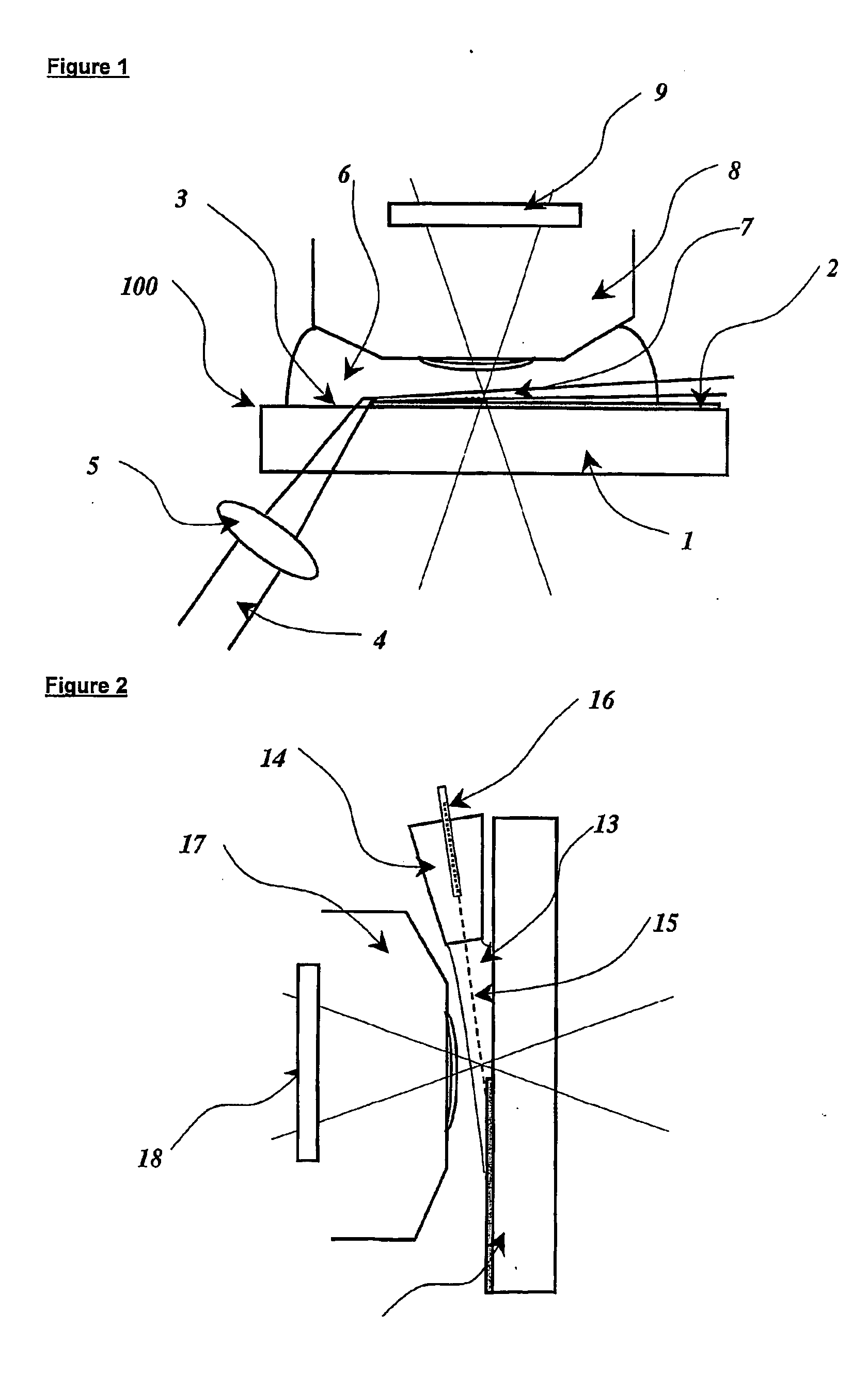
[0051] Referring to FIG. 1, apparatus in accordance with the invention comprises an instrument element 100 having an optically transparent substrate 1, typically a glass or silica prism or flat, onto part of which is deposited a thin film of metal 2, typically 30-80 nm depth of e.g. gold, silver, aluminium or chrome deposited by any suitable sputtering, vapour phase, electrochemical or other deposition means. The optical substrate is only partially covered by the metal film 2, a portion 3 of the surface being left uncoated. A light beam of suitable collimation, intensity, polarisation and wavelength or wavelength range 4 is focused by lens 5 to be incident on the optical element such that the beam strikes the surface of the optical element in the region 3 which is not covered by the metal film 2 but which is adjacent to the metallised region at an angle at which, when a sample of liquid 6 containing a suspension of particles 7 is placed onto the surface of the optical element 100, t...


PUM

PropertyMeasurementUnit
diameteraaaaaaaaaa
sizeaaaaaaaaaa
transparentaaaaaaaaaa

Abstract

Method and apparatus for the single particle detection of submicron structures such as biological molecules and viruses utilises an optical element (100) comprising an optically transparent substrate (1) partially coated with a thin film of me (2) illuminated with an optical beam (4) incident on a non-metal coated region (3) of the surface of the optical element at a point adjacent or close to the metal coated region of the optical element such that the beam propagates above but close and substantially parallel to the metal surface defining a measurement zone from within which submicron particles (7) contained in a sample (6) placed in contact with the optical element scatter or emit light which can be detected in the far field by conventional photodetection systems. The apparatus can be configured in a flow cell or optical microscope configuration.

Description

[0001] The present invention relates to the optical detection and analysis of particulates of nanometre, sub-micron or micron dimensions. [0002] A large number of principles and techniques exist by which particles can be analysed in terms of their number, size, shape, composition and motion. Historically, the observation and characterisation of particles lies in the domain of microscopy in which highly magnified images of particles are generated through the use of high powered lensed systems and which can be seen directly by eye or can be captured by camera for subsequent interpretation by the operator or by an image analysis system. [0003] There are many types of microscope systems capable of characterising the particle in terms of its interaction with the incident illumination. For instance, the particle may selectively absorb certain wavelengths of the light such as in differential absorption, the technique most common in conventional transmission microscopy. Other microscopical ...

Claims


Application Information

Patent Timeline
Patent Type & Authority Applications(United States)
IPC IPC(8): G01N15/00G01N15/02G01N15/14G01N21/49
CPCG01N15/02G01N21/49G01N15/14G01N15/0205
Inventor CARR, ROBERT JEFFREY GEDDES
Owner MALVERN INSTRUMENTS
Why Eureka
Try Eureka