Braze alloy for drilling applications

a brazing alloy and drilling technology, applied in the direction of drilling apparatus, tool workpiece connection, manufacturing tools, etc., can solve the problems of limiting the number of alloys, increasing the chance of cutting elements cracking and chipping during drilling, and cutters brazed at higher temperatures have a higher chance of cracking and chipping in the field

a brazing alloy and drilling technology, applied in the direction of drilling apparatus, tool workpiece connection, manufacturing tools, etc., can solve the problems of limiting the number of alloys, increasing the chance of cutting elements cracking and chipping during drilling, and cutters brazed at higher temperatures have a higher chance of cracking and chipping in the field

US20050087371A1Inactive Publication Date: 2005-04-28SMITH INT INC +1

Image

  • Braze alloy for drilling applications
  • Braze alloy for drilling applications
  • Braze alloy for drilling applications

Examples


Embodiment Construction

[0023] The present invention provides down hole cutting tools and methods for manufacturing down hole cutting tools which include the use of an improved braze alloy that has been shown to be useful in drilling tool applications.

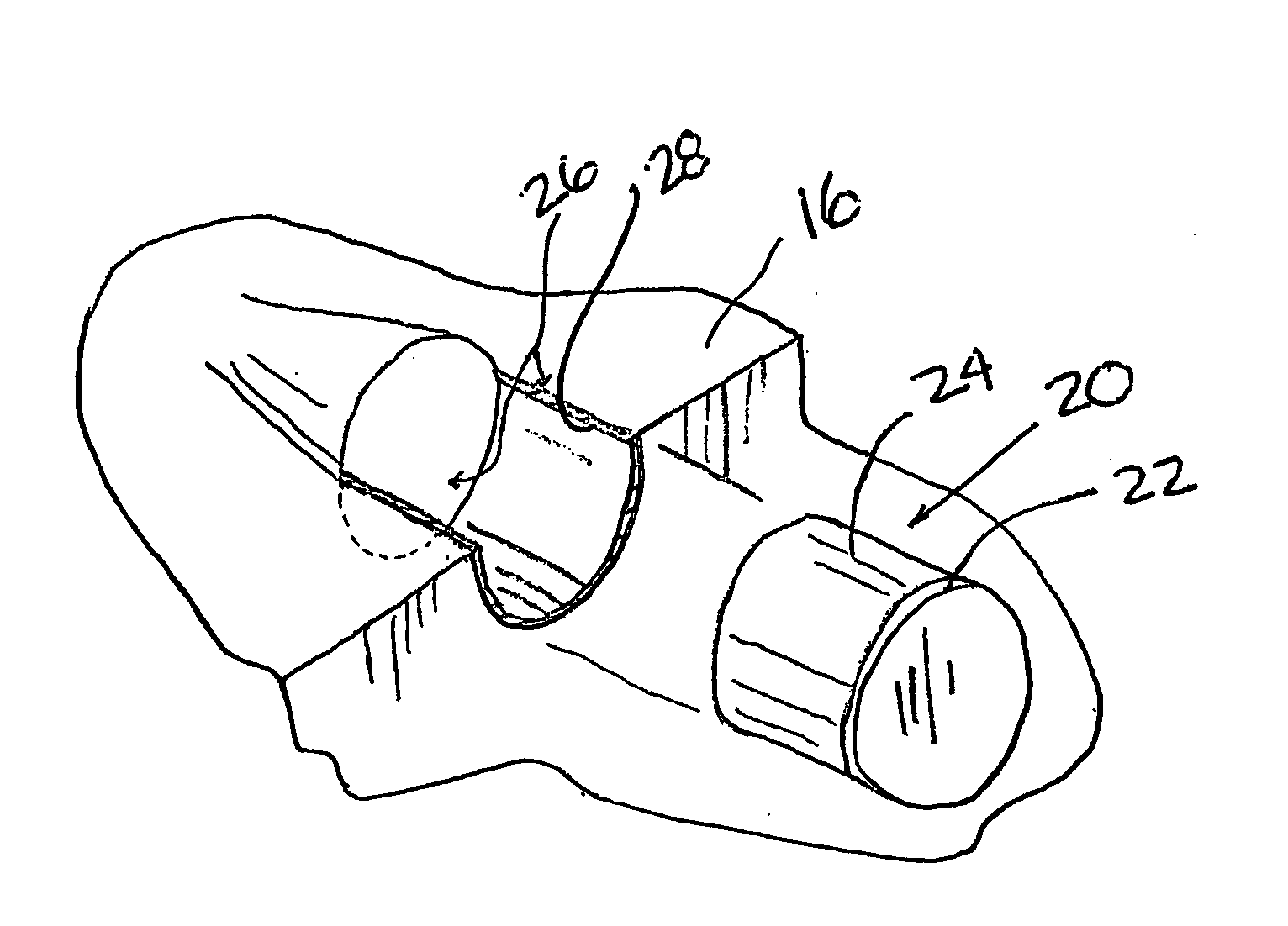
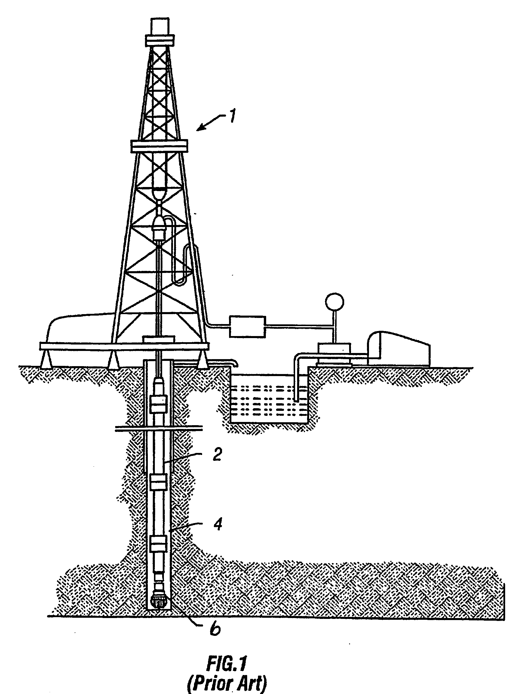
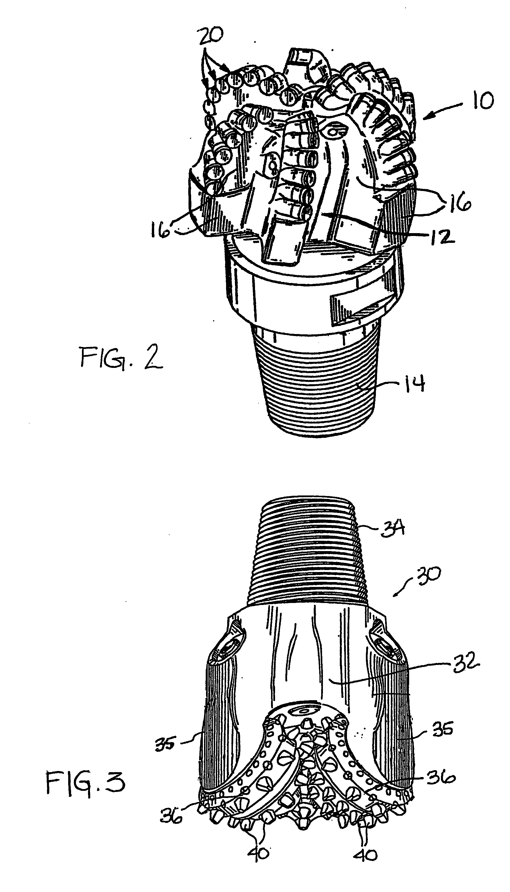
[0024] In one aspect, the present invention provides a down hole cutting tool which includes a braze alloy comprising between about 0.5% and about 10% by weight of at least one element selected from the group of gallium (Ga), indium (In), and thallium (Tl), or any combination thereof. The braze alloy may be used to braze cutting elements to a cutting element support structure (e.g., cutting face, blades, cones, etc.) of a drilling tool. The drilling tool may include a tool body with a cutting element support structure connected to or integrally formed with the tool body. The tool may comprise a drill bit such as a fixed cutter drill, roller cone drill bit, or a hammer bit. In other embodiments, the tool may comprise a reaming tool, a fishing tool, milling to...


PUM

PropertyMeasurementUnit
temperaturesaaaaaaaaaa

Abstract

A down hole cutting tool includes a cutting element support structure. The cutting element support structure has at least one cavity formed therein. A cutting element is disposed in the cavity. Braze alloy is also disposed in the cavity between the cutting element and the cutting element support structure. The braze alloy comprises between about 0.5% and about 10% by weight of at least one selected from the group of gallium (Ga), indium (In), thallium (Tl). Methods for building a down hole tool using the braze alloy are also disclosed.

Description

CROSS-REFERENCE TO RELATED APPLICATIONS [0001] Not applicable. STATEMENT REGARDING FEDERALLY SPONSORED RESEARCH OR DEVELOPMENT [0002] Not applicable. BACKGROUND OF INVENTION [0003] 1. Field of the Invention [0004] The present invention relates to drilling tools for drilling bore holes in earth formations. More particularly, the present invention provides drilling tools and methods for manufacturing drilling tools which include the use of a new braze alloy for brazing cutting elements in drilling tool applications, especially cutting elements including ultrahard material, such as polycrystalline diamond. [0005] 2. Background Art [0006] Earth boring tools, and in particular drill bits, are commonly used in the oil and gas industry for drilling well bores. FIG. 1 shows one example of a conventional drilling system for drilling through earth formation. The drilling system includes a drilling rig 1 used to turn a drill string 2 which extends downward into a well bore 4. Connected to the ...

Claims


Application Information

Patent Timeline
28 Apr 2005
Publication
US20050087371A1
IPC
B23B27/14; B23K1/00; B23K35/30
CPC
B23B27/148; B23B2222/28; B23B2226/125; B23K2201/20; B23B2240/08; B23K1/0008; B23K35/3006; B23B2226/315
Inventors
KEMBAIYAN, KUMAR T.