Pocket analyser

a pocket-sized, vibrating technology, applied in the direction of biological testing, enzymology, after-treatment of biomass, etc., can solve the problems of extended sampling time, poor sensitivity of flow cells that rely on convective and diffusional etc., to improve sensitivity, reduce sampling time, and enhance mass transport of analyte

a pocket-sized, vibrating technology, applied in the direction of biological testing, enzymology, after-treatment of biomass, etc., can solve the problems of extended sampling time, poor sensitivity of flow cells that rely on convective and diffusional etc., to improve sensitivity, reduce sampling time, and enhance mass transport of analyte

US20050087442A1Inactive Publication Date: 2005-04-28ELKIND JEROME L

Image

  • Pocket analyser
  • Pocket analyser
  • Pocket analyser

Examples


Embodiment Construction

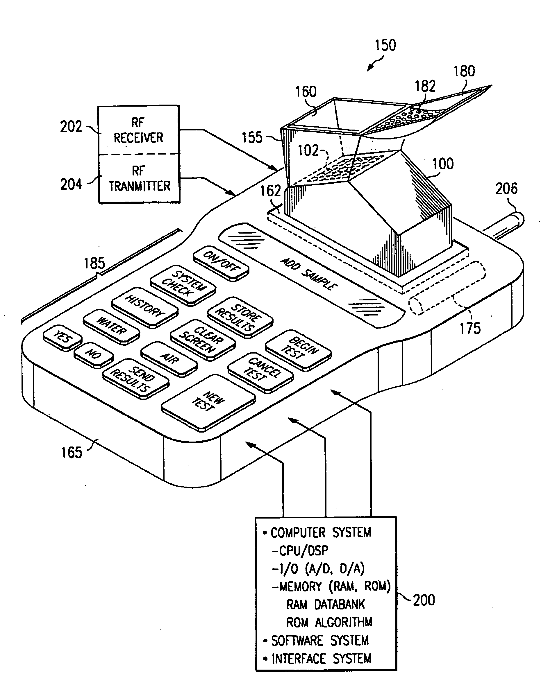
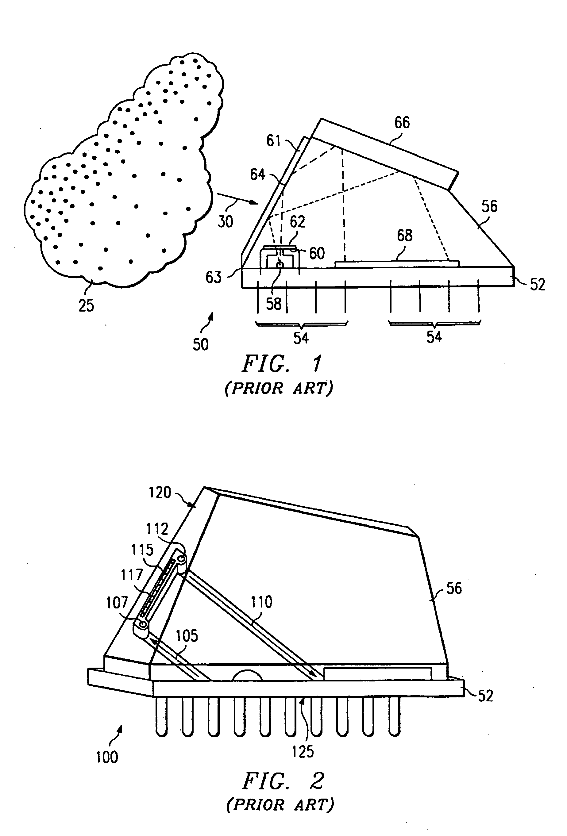
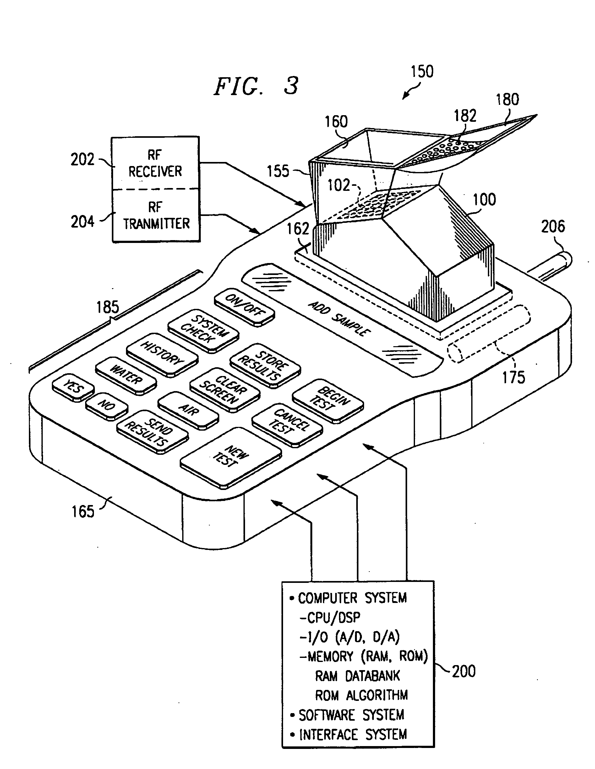
[0019]FIG. 1 illustrates a prior art integrally formed optically based Surface Plasmon Resonance (SPR) sensor 50 in close proximity to a sample 25 analyte of interest that is a liquid. The sample 25 may be any liquid (bio)chemical substance for which an indicator interaction is known and which can be formed into thin biosensing layer 61. The film is deposited on a surface 63 of the sensor and exposed to the sample 25 during analysis. Various ways of bringing the sample 25 in contact with the surface 63 may be employed such as by dipping, dropping or by using a flow cell.

[0020] As shown, a substrate 52 forms a device platform to which a light transmissive housing 56 is coupled. The housing material can be plastic, glass or other similar optic coupling substance. A light source is preferably located above or within the substrate 52 and has an aperture 58 there over allowing light to pass. In one embodiment, the light source is a single high intensity light emitting diode. A polarizer...


PUM

PropertyMeasurementUnit
mass transportaaaaaaaaaa
light reflection propertiesaaaaaaaaaa
molecular weightaaaaaaaaaa

Abstract

An agitated flow cell had a micro / miniature vibrator device such as pager motor to agitate the flow cell and its associated sensor to bring fresh analyte to the sensor surface without the need for microfluidic channels, pumps or valves. The agitated flow cell improves the confidence measure of a given sample reading by directing the flow of sample to the sensor / sample interface in a substantially shorter period of time than that required by flow cells that rely on diffusion of analyte molecules through the liquid depletion region in order to bring the sample reliably in contact with the sensor's biosensing film.

Description

BACKGROUND OF THE INVENTION [0001] 1. Field of the Invention [0002] This invention relates generally to analytical testing instrumentation, and more particularly to an agitated well or fluid chamber having a micro / miniature vibrator device such as a pager motor to agitate the well / fluid chamber, its contents and its associated sensor to enable mixing of dehydrated reagents and bring analyte to the sensor surface without the need for microfluidic channels, pumps or valves. [0003] 2. Description of the Prior Art [0004] Most analytical measurements have historically been made in a central laboratory, on sophisticated equipment by highly trained personnel. Modern trends have demonstrated a need for a more de-centralized testing methodology where analytical measurements are actually made at the sample collection site, since this is generally the place where the results are needed. [0005] One miniaturized sensor platform with integrated channels for controlling the flow of sample over a s...

Claims


Application Information

Patent Timeline
28 Apr 2005
Publication
US20050087442A1
IPC
G01N21/05; G01N21/55; G01N35/00
CPC
G01N21/05; G01N2021/0346; G01N2035/00524; G01N21/553
Inventors
ELKIND, JEROME L.