
Substrate preparation using megasonic coupling fluid meniscus and methods, apparatus, and systems for implementing the same

Inactive Publication Date: 2010-10-12
LAM RES CORP
View PDF4 Cites 10 Cited by
  • Summary
  • Abstract
  • Description
  • Claims
  • Application Information

AI Technical Summary

Benefits of technology

[0009]Broadly speaking, the present invention fills these needs by providing a method, apparatus, and system for improving a semiconductor substrate preparation and / or cleaning operations without substantially damaging semiconductor devices formed on the substrate frontsides. In one example, the present invention improves substrate preparation and / or cleaning operations by enhancing a mass transport of a preparation chemical to a reaction interface defined between the material to be removed and the substrate frontside. According to one aspect, the mass transport of the preparation chemistry to the reaction interface is achieved by applying megasonic energy to a backside of the substrate and the transmission of the megasonic energy to the reaction interface through a megasonic coupling fluid meniscus and the substrate. In accordance with one aspect, the megasonic coupling fluid meniscus having a lower temperature can be implemented to isolate a higher temperature condition on the substrate frontside (i.e., the process side) from a megasonic coupling proximity head defined on the substrate backside.
[0011]In one embodiment, an apparatus for preparing a substrate is provided. The apparatus includes a proximity head and a megasonic proximity head. The proximity head is configured to be applied to a substrate frontside and is capable of generating a preparation meniscus on the substrate frontside. The preparation meniscus includes a preparation chemistry that is configured to remove a material defined on the substrate frontside. The megasonic proximity head is configured to be applied to a substrate backside, and is capable of generating a coupling meniscus on the substrate backside. The megasonic proximity head is further capable of imparting megasonic energy to the coupling meniscus. The megasonic energy imparted to the coupling meniscus is configured to enhance a mass transport of the preparation chemistry through a material to be removed on the substrate frontside.
[0012]According to another embodiment of the present invention, a method for enhancing the mass transport of a chemistry in a material to be removed is provided. The method includes applying the chemistry on the material to be removed and forming a back meniscus on a second side of the substrate. The material to be removed is defined on a first side of a substrate. Megasonic energy is applied to the back meniscus. The megasonic energy is transmitted to an interface defined between the material to be removed and the first side of the substrate through the back meniscus such that the mass transport of the chemistry through the material to be removed is enhanced.
[0013]According to yet another embodiment of the present invention, a substrate preparation system is provided. The system includes a proximity head and a megasonic proximity head. The megasonic proximity head includes a resonator and a crystal. The resonator has a first side and a second side and the first side of the resonator faces the substrate backside. The crystal is defined on the second side of the resonator. The vibration of the crystal is configured to generate megasonic energy. The proximity head is configured to be applied to a substrate frontside and is capable of generating a preparation meniscus on the substrate frontside. The preparation meniscus includes a preparation chemistry that is configured to remove a material to be removed defined on the substrate frontside. The megasonic proximity head is configured to be applied to a substrate backside and is capable of generating megasonic energy. The megasonic energy is configured to enhance a mass transport of the preparation chemistry through the material to be removed.
[0015]The advantages of the present invention are numerous. Most notably, the present invention can substantially reduce undesirable damage to the semiconductor devices formed over the substrate frontside by transmission of the megasonic energy to the interface through the substrate backside and the substrate. Furthermore, megasonic energy is not being applied directly to the semiconductor devices defined on the substrate frontside, thus substantially reducing the possibility of dislodging or damaging the semiconductor features formed therein. Yet further, enhancing the mass transport of the preparation chemistry through the material to be removed requires a lower level of megasonic energy.

Problems solved by technology

The soaking of batches of semiconductor wafers in tanks filled with chemicals is disfavored, as chemicals can be costly, and the wet operation can be very time consuming.
Achieving the latter, however, can be very costly as the megasonic equipment and the chemicals implemented for photoresist stripping have to be chemically compatible.
Furthermore, applying megasonic to the semiconductor wafer frontside (i.e., the active side or top surface) can undesirably damage the semiconductor devices, thus resulting in defective semiconductor wafers.
Failure to remove the particulate contaminants from the semiconductor wafer frontside can have detrimental effects on the performance of the semiconductor devices formed thereon, ultimately resulting in defective semiconductor wafers.
In the same manner, failure to adequately and properly clean and process semiconductor wafer backside (i.e., non-active side) can be detrimental.
For instance, unfortunately, residues and contaminant particulates on semiconductor wafer backsides can migrate from the semiconductor wafer backside to the semiconductor wafer frontside.
Additionally, any residual fluid on the semiconductor wafer backside can migrate to the substrate frontside, thus re-contaminating the otherwise cleaned semiconductor wafer frontside.
Furthermore, the backside contaminants can undesirably migrate from the tools or steps of one process to tools and steps of the following processes, thus contaminating the subsequent processes.
Consequently, the migration of residual fluid can compromise the quality of the substrate preparation operations, and as such, is disfavored.
Furthermore, megasonic energy is not being applied directly to the semiconductor devices defined on the substrate frontside, thus substantially reducing the possibility of dislodging or damaging the semiconductor features formed therein.

Method used


Image

  • Substrate preparation using megasonic coupling fluid meniscus and methods, apparatus, and systems for implementing the same
  • Substrate preparation using megasonic coupling fluid meniscus and methods, apparatus, and systems for implementing the same
  • Substrate preparation using megasonic coupling fluid meniscus and methods, apparatus, and systems for implementing the same

Examples


Embodiment Construction

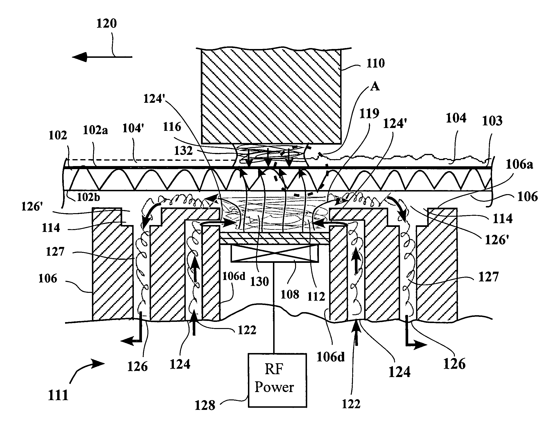
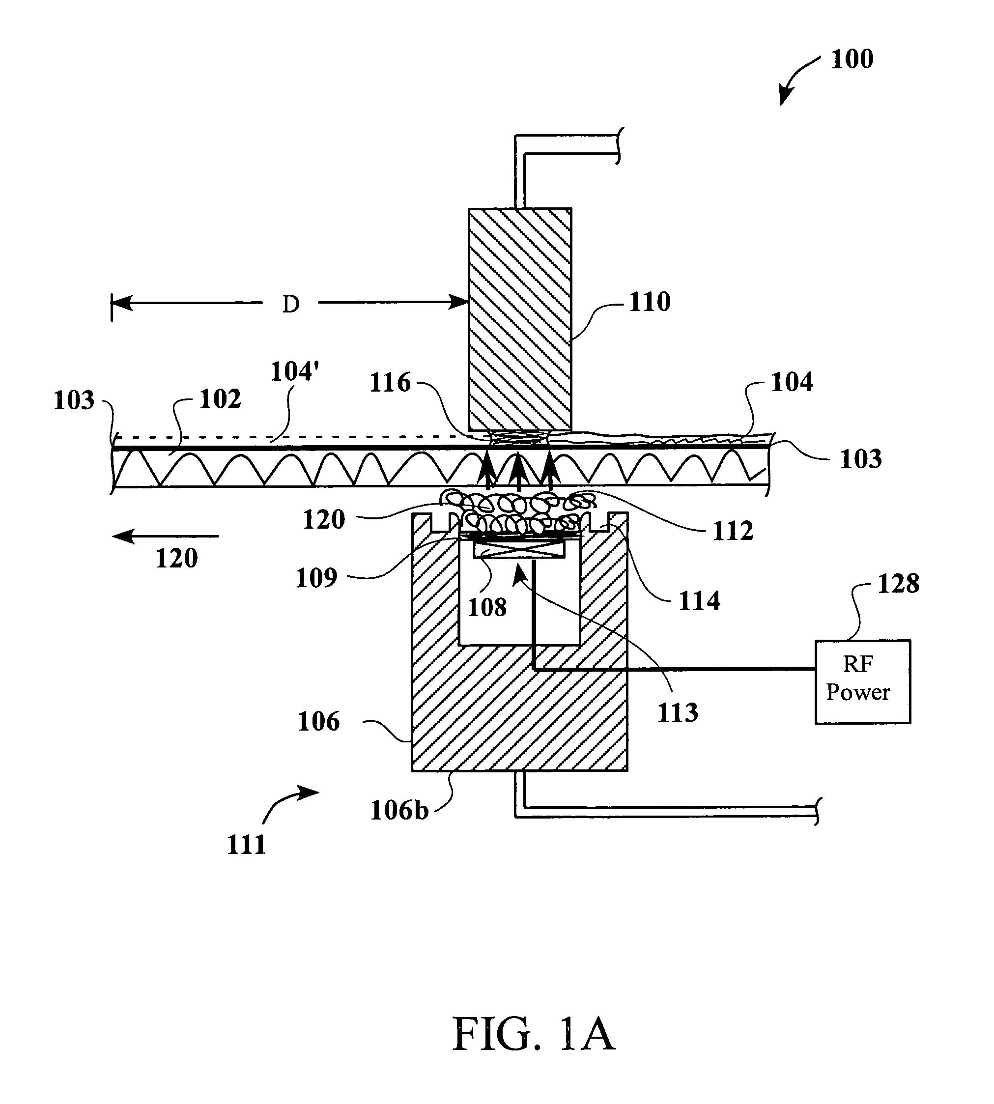
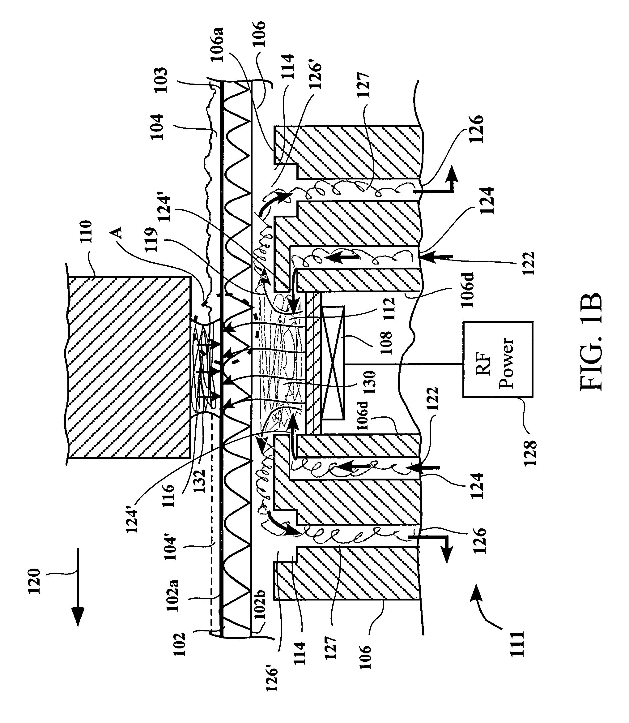
[0031]An invention capable of improving substrate preparation and / or cleaning operations without substantially damaging semiconductor devices formed on substrate frontsides is provided. In one example, the present invention improves substrate preparation and / or cleaning operations by enhancing a mass transport of preparation chemistry to a reaction interface on the substrate frontside. According to one aspect, the enhancing of the mass transport of the preparation chemistry to the reaction interface is achieved by imparting megasonic energy to the interface through a megasonic coupling fluid meniscus coupled to a backside of the substrate. In one example, the megasonic energy imparted to the reaction interface further assists in breaking a bond or a force between the material to be removed and / or the residues or particulate contaminants, and the substrate frontside at the reaction interface, thus resulting in the removed of the residues, particulate contaminants, and / or the material...


PUM


Abstract

An apparatus for preparing a substrate is provided. The apparatus includes a proximity head and a megasonic proximity head. The proximity head is configured to be applied to a substrate frontside and is capable of generating a preparation meniscus on the substrate frontside. The preparation meniscus includes a preparation chemistry that is configured to remove a material defined on the substrate frontside. The megasonic proximity head is configured to be applied to a substrate backside, and is capable of generating a coupling meniscus on the substrate backside. The megasonic proximity head is further capable of imparting megasonic energy to the coupling meniscus. The megasonic energy imparted to the coupling meniscus is configured to enhance a mass transport of the preparation chemistry through a material to be removed on the substrate frontside.

Description

CROSS-REFERENCE TO RELATED APPLICATIONS[0001]This application is a continuation-in-part of U.S. patent application Ser. No. 10 / 261,839, filed on Sep. 30, 2002, now U.S. Pat. No. 7,234,477 and entitled “METHOD AND APPARATUS FOR DRYING SEMICONDUCTOR WAFER SURFACES USING A PLURALITY OF INLETS AND OUTLETS HELD IN CLOSE PROXIMITY TO THE WAFER SURFACES,” from which priority under 35 U.S.C. §120 is claimed. The disclosure of this application is incorporated herein by reference in its entirety.BACKGROUND[0002]The present invention relates generally to substrate preparation and / or cleaning and, more particularly, to systems, apparatus, and methods for improving preparation and / or cleaning of semiconductor substrate front surfaces.DESCRIPTION OF THE RELATED ART[0003]The fabrication of semiconductor devices involves numerous processing operations. These operations include, for example, dopant implants, gate oxide generation, inter-metal oxide depositions, metallization depositions, photolithog...

Claims


Application Information

Patent Timeline
IPC IPC(8): B08B3/04
CPCB08B3/123G03F7/30H01L21/67028H01L21/67034H01L21/67051Y10S134/902
Inventor BOYD, JOHN M.REDEKER, FRITZ C.YUN, SEOKMIN
Owner LAM RES CORP
Learn More