

Voltage regulator
a voltage regulator and voltage regulation technology, applied in the direction of electric variable regulation, process and machine control, instruments, etc., can solve the problems of increasing current consumption and sacrificed load fluctuation characteristics, and achieve the effect of improving an undershoot characteristic and low current consumption
- Summary
- Abstract
- Description
- Claims
- Application Information
AI Technical Summary
Benefits of technology
Problems solved by technology
Method used
Image

Examples
first embodiment
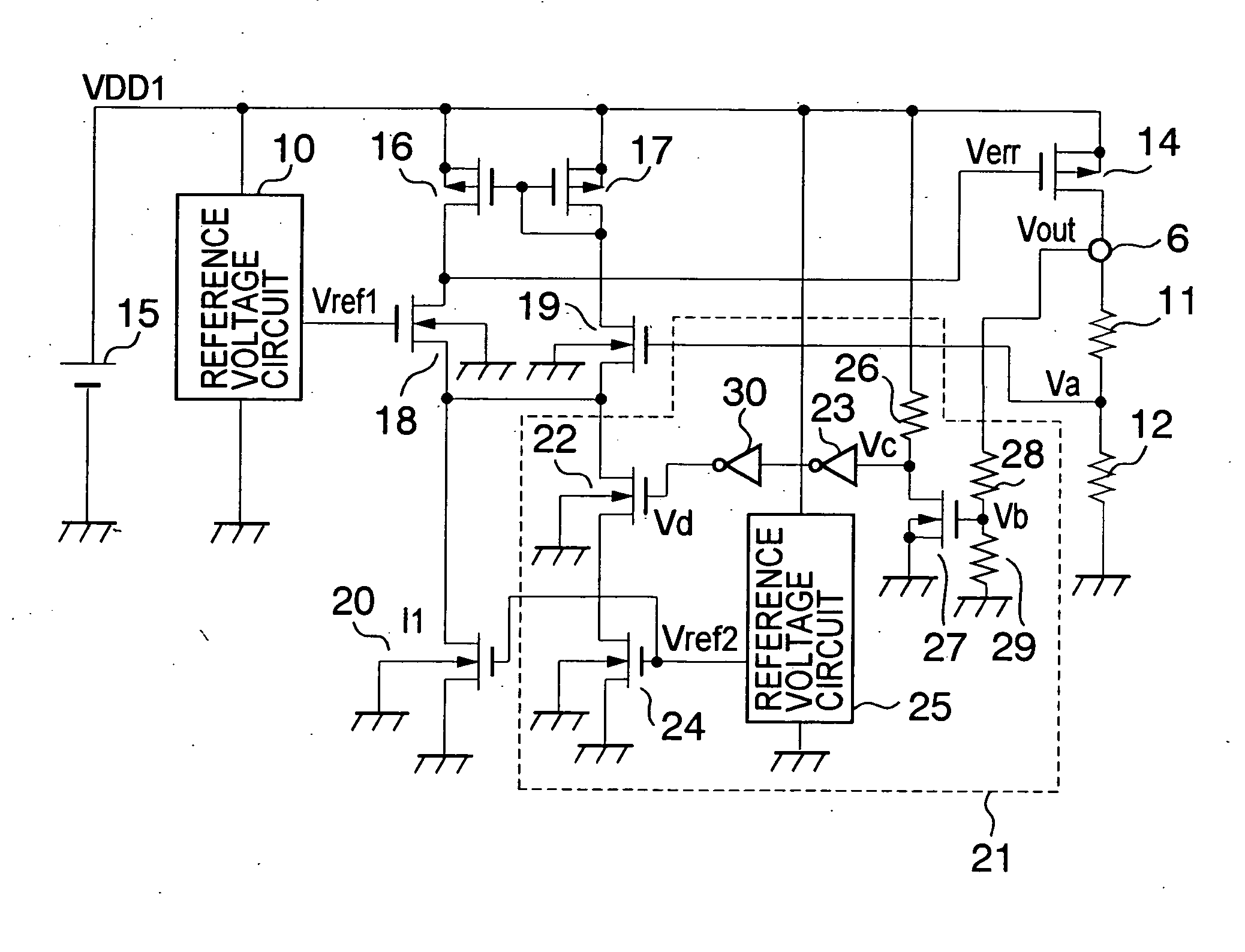
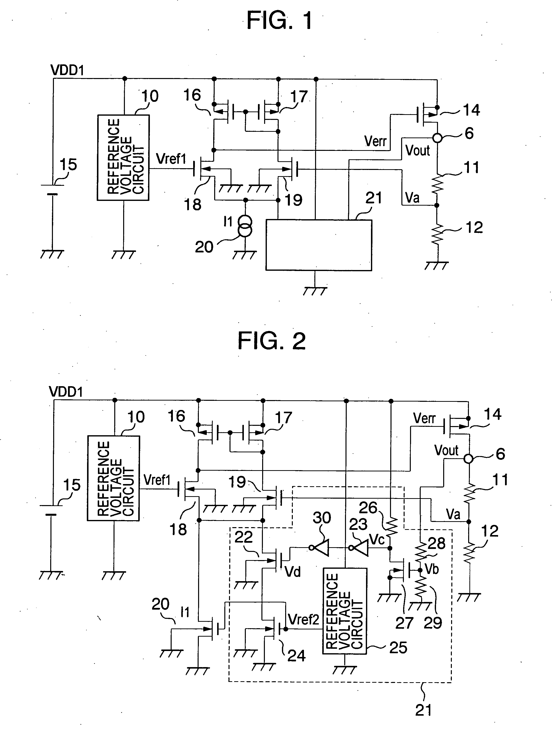
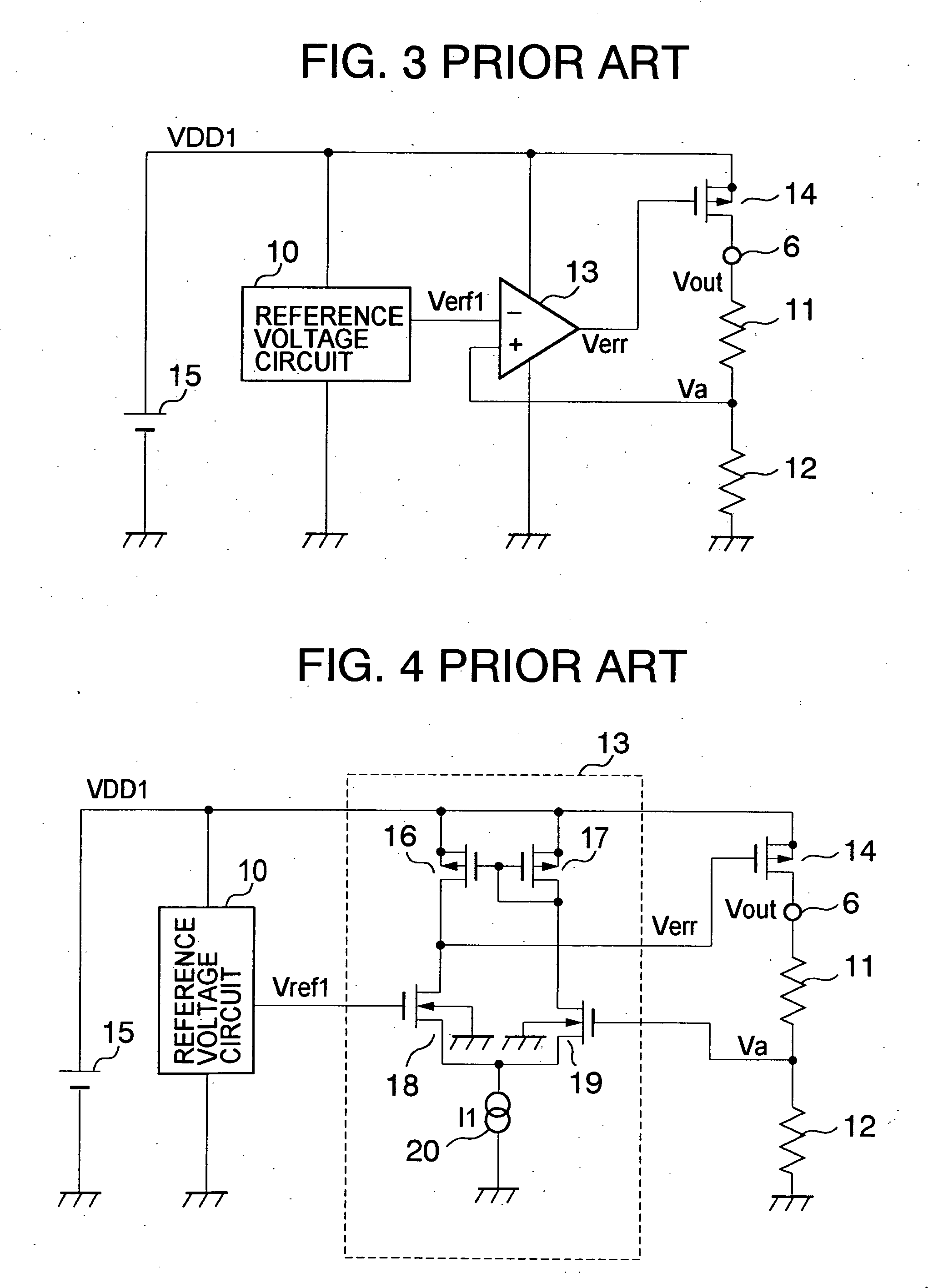
[0026]FIG. 1 is a circuit diagram showing a voltage regulator according to a first embodiment of the present invention. A difference of FIG. 1 from FIG. 4 resides in the provision of a current adder circuit 21. The current adder circuit 21 operates to increase the operating current of an error amplifier in a state where it is detected that a constant voltage to which an output voltage Vout is to be controlled is lower than a desired value.
[0027] The current adder circuit 21 includes, for example as shown in FIG. 2, a breeder resistor 28 and a breeder resistor 29 which divide the output voltage Vout, an n-channel MOS transistor 27 whose on / off operation is controlled by means of a voltage Vb at a node of the breeder resistor 28 and the breeder resistor 29, and a resistor 26 for pulling up a drain of the n-channel MOS transistor 27. The current adder circuit 21 also includes an inverter 23 and an inverter 30 which input a voltage Vc at a node of the drain of the n-channel MOS transis...
second embodiment
[0032]FIG. 5 is a circuit diagram showing a voltage regulator in accordance with a second embodiment of the present invention.
[0033] In the voltage regulator of the first embodiment, the reference voltage Vref2 is applied to the gate of the n-channel MOS transistor that structures the constant current circuit 20 and the n-channel MOS transistor 24. In the voltage regulator of the second embodiment, a reference voltage Vref3 is newly added so as to apply the reference voltages to the respective n-channel transistors, independently. When the values of the reference voltages Vref2 and Vref3 are arbitrarily given, a current that is increased by the current adder circuit 21 can be varied. Thus, there is an advantage in that the current can be arbitrarily set.
third embodiment
[0034]FIG. 6 is a circuit diagram showing a voltage regulator in accordance with a third embodiment of the present invention.
[0035] In the voltage regulator of the third embodiment, the breeder resistor 28 and the breeder resistor 29 are made up of a variable resistor, respectively. The value of Vb is controlled with the above structure, as a result of which a relationship between a current that is added to the error amplifier and the output voltage Vout at the time of a heavy load can be arbitrarily controlled. Hence, the invention can widely be applied to each product, and it is possible to optimally improve an undershooting characteristic and reduce the current consumption.
[0036] In the descriptions of the above first to third embodiments, the current adder circuit 21 is structured as shown in FIG. 2, but it is apparent that the same effects can be obtained even in other circuit structures having the identical functions.
PUM
 Abstract
Description
Claims
Application Information