Optical scanning apparatus and image forming apparatus

Inactive Publication Date: 2005-04-28
SEIKO EPSON CORP
View PDF12 Cites 16 Cited by
  • Summary
  • Abstract
  • Description
  • Claims
  • Application Information

AI Technical Summary

Benefits of technology

[0014] It is a further object of the present invention is to provide an optical scanning apparatus which securely attains a larger deflection angle of a light beam than the maxim

Problems solved by technology

Thus, there is a problem that since the vibration amplitude of the vibration mirrors does not stay stable when the temperature in an environment around the vibration mirrors changes, i

Method used


Image

  • Optical scanning apparatus and image forming apparatus
  • Optical scanning apparatus and image forming apparatus
  • Optical scanning apparatus and image forming apparatus

Examples


first embodiment

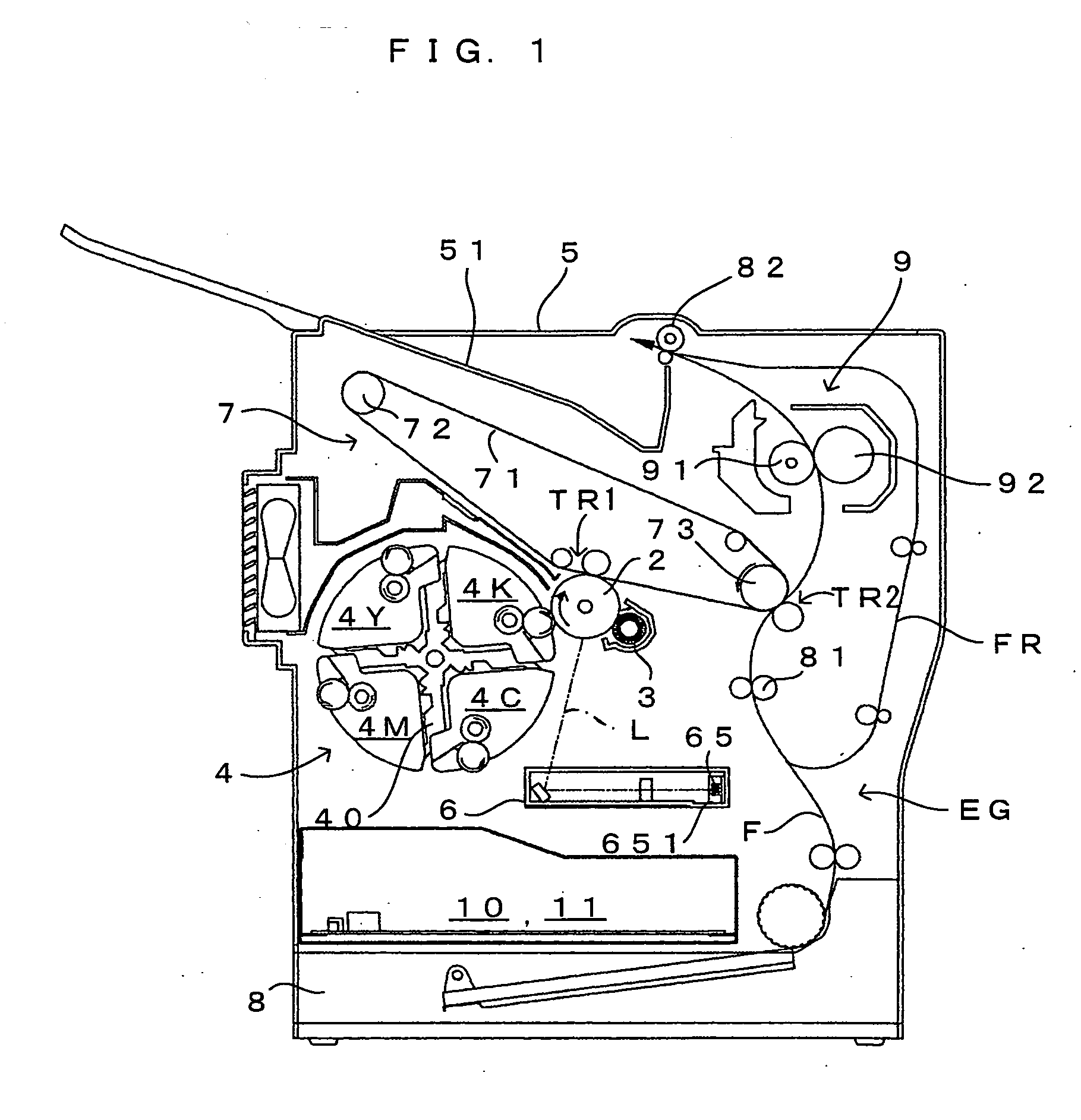
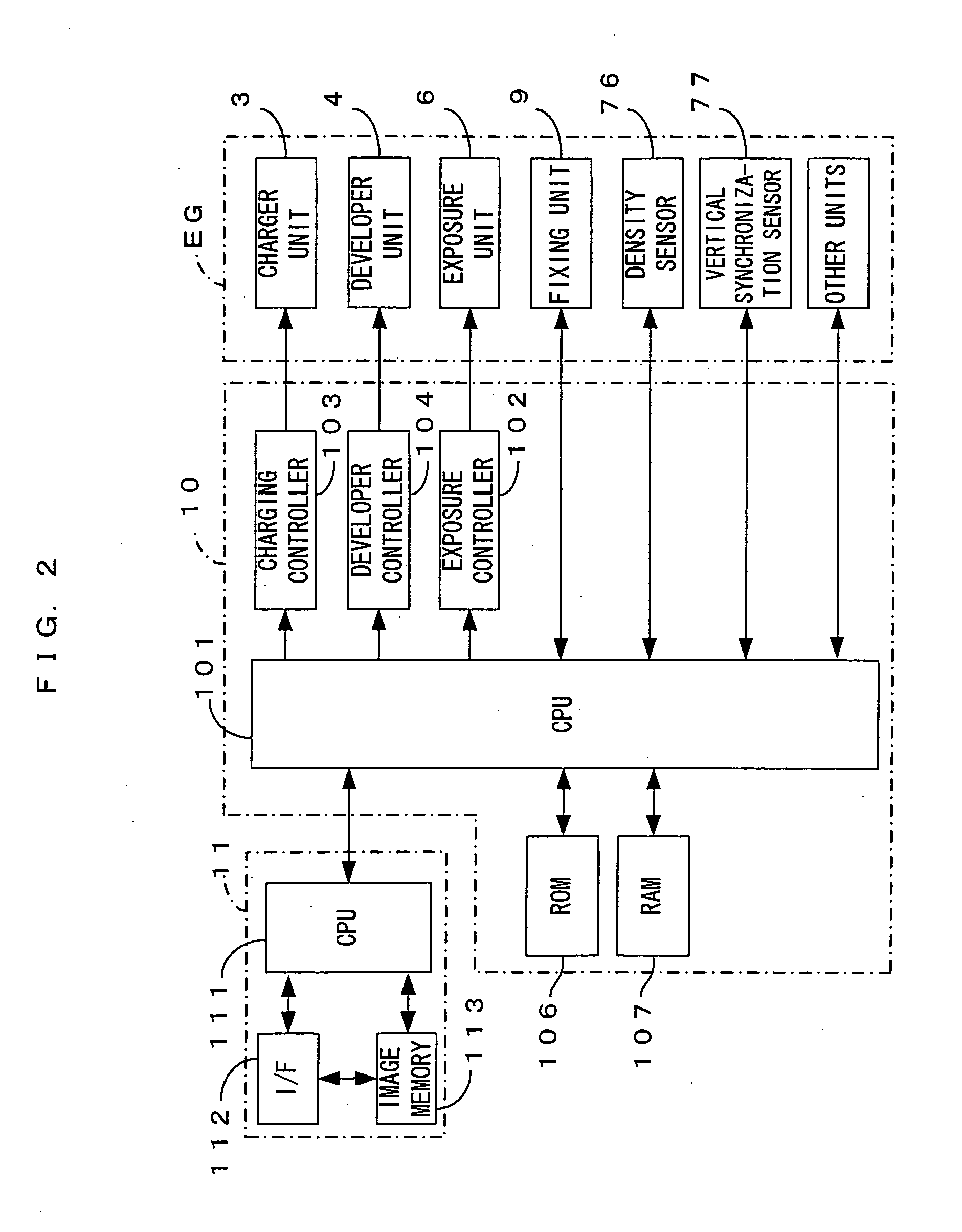
[0035]FIG. 1 is a drawing of an image forming apparatus equipped with an exposure unit which is a first embodiment of an optical scanning apparatus according to the present invention. FIG. 2 is a block diagram showing the electric structure of the image forming apparatus which is shown in FIG. 1. This image forming apparatus is a color printer of the so-called 4-cycle method. In this image forming apparatus, when a print command is fed to a main controller 11 from an external apparatus such as a host computer in response to an image formation request from a user, an engine controller 10 controls respective portions of an engine part EG in accordance with the print command from a CPU 111 of the main controller 11, and an image which corresponds to the print command is formed on a sheet which may be a copy paper, a transfer paper, a plain paper or a transparency for an overhead projector.

[0036] In the engine part EG; a photosensitive member 2 (which corresponds to the “latent image c...

second embodiment

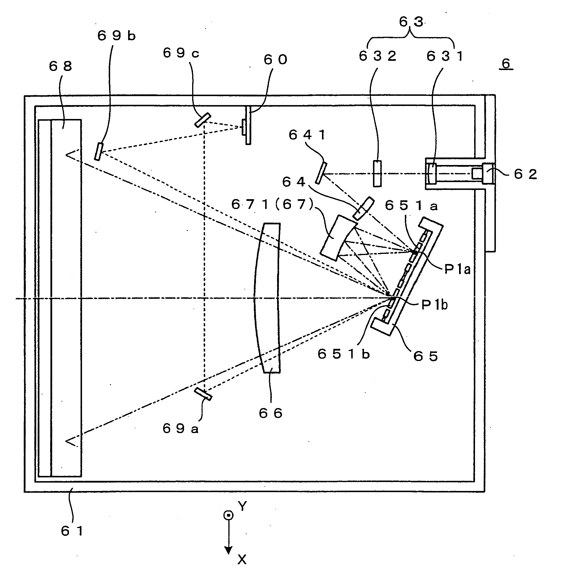
[0068]FIGS. 10 and 11 are main-scanning cross sectional views which shows a second embodiment of the optical scanning apparatus according to the present invention. FIG. 12 is a sub-scanning cross sectional view of the optical scanning apparatus which is shown in FIG. 10. A major difference of the exposure unit 6 of the second embodiment from the first embodiment lies in the structure of the deflecting element 65. That is, in the second embodiment, as shown in FIG. 12, the first and the second deflection mirror surfaces 651a and 651b are arranged side by side in the sub scanning direction Y In the exposure unit 6 having such a structure, the light beam from the single laser source 62 impinges upon the cylindrical lens 632 which has power only along the sub scanning direction Y as shown in FIG. 12, after shaped into collimated light of a proper size by the collimator lens 631. Meanwhile, the light beam transmitted by the cylindrical lens 632 is returned by the return mirror 641 toward...

third embodiment

[0070]FIG. 13 is a drawing which shows a third embodiment of the optical scanning apparatus according to the present invention. FIG. 13 is a main-scanning cross sectional view showing the structure of an exposure unit (optical scanning apparatus) which is disposed inside the image forming apparatus which is shown in FIG. 1. FIG. 14 shows a transmission optical system which is one of components which form the exposure unit. FIGS. 15 and 16 are drawings of a deflecting element which is one of the components of the exposure unit. A major difference of this embodiment from the first and the second embodiments above lies in the structure of a transmission optical system 87, which transmits a light beam between a first deflection mirror surface 851a and a second deflection mirror surface 851b, and the structure of deflector 85, as shown in FIG. 13. The structure and operations of the exposure unit will now be described in detail referring to these drawings, with a main focus on the differ...


PUM


Abstract

A mirror driver drives deflection mirror surfaces into a pivoting action at a frequency belonging to a first drive frequency band in which the high-frequency side of a first resonance frequency band partially overlaps the low-frequency side of a second resonance frequency band, so that the deflection mirror surfaces deflect a light beam. Hence, the deflection angles of light beams change, while canceling out each other the changes of the deflection angles of the light beams deflected by the deflection mirror surfaces owing to changes of resonance characteristics. Because of this, even when the resonance characteristics change, it is possible to stabilize the deflection angle of the light beam deflected by the first deflection mirror surface and further deflected by the second deflection mirror surface.

Description

CROSS REFERENCE TO RELATED APPLICATION [0001] The disclosure of Japanese Patent Applications enumerated below including specification, drawings and claims is incorporated herein by reference in its entirety: [0002] No.2003-324196 filed Sep. 17, 2003; and [0003] No.2003-336829 filed Sep. 29, 2003. BACKGROUND OF THE INVENTION [0004] 1. Field of the Invention [0005] The present invention relates to an optical scanning apparatus in which a plurality of deflection mirror surfaces are used for scanning with a light beam, e.g., an optical scanning apparatus. In the apparatus, a light beam deflected by one deflection mirror surface is deflected further by another deflection mirror surface and the deflection angle of the light beam accordingly increases, and also to an image forming apparatus which comprises such an optical scanning apparatus. [0006] 2. Description of the Related Art [0007] In an attempt to increase the deflection angle of a light beam, a conventional optical scanning appara...

Claims


Application Information

Patent Timeline
IPC IPC(8): B41J2/47G02B26/08G02B26/10
CPCB41J2/471G02B26/101G02B26/0841
Inventor NOMURA, YUJIROIKUMA, KEN
Owner SEIKO EPSON CORP
Why Eureka
Try Eureka