Apparatus for measuring oil oxidation using fluorescent light reflected from oil

a technology of fluorescent light and oil, which is applied in the direction of fluorescence/phosphorescence, instruments, and analysis by material excitation, etc., can solve the problems of affecting the performance of the engine, so as to achieve the effect of reducing the cost of the instrumen

Inactive Publication Date: 2005-04-28
KOREA INST OF SCI & TECH
View PDF6 Cites 36 Cited by
  • Summary
  • Abstract
  • Description
  • Claims
  • Application Information

AI Technical Summary

Benefits of technology

[0021] Consistent with the foregoing object, and in accordance with the invention as embodied broadly described herein, an apparatus for measuring oil oxidation using fluorescent light reflected from oil is disclosed in one embodiment of the present invention, comprising a light-emitting means; a plurality of first light-transmitting means, which extend from the light-emitting means, for introducing light into oil at a plurality of different incident points; a plurality of light-reflecting means, which are immersed in the oil and disposed opposite the incident points, wherein each of the light-reflecting means is located at a different distance from the incident points; a plurality of second light-transmitting means, which extend from the incident points; a plurality of light-receiving means, which are connected to the second light-transmitting means, for receiving the light and generating signal outputs corresponding to the received light; and a control portion, which calculates a fluorescence quantum yield and a light absorption coefficient of the oil, based upon the signals from the light-receiving means, and compares the calculated fluorescence quantum yield and light absorption coefficient with reference fluorescence quantum yields and light absorption coefficients pre-stored in the control portion to determine the oil oxidation.

Problems solved by technology

The physical degradation of the oil is usually caused by metallic wear particles and dusts introduced into the oil from outside.
These contaminants cause excessive wear on the surfaces of engine components, like cylinders, bearings, cylinder walls, and pistons, thereby deteriorating engine performance considerably.
In addition, the chemical degradation is predominantly caused by moisture, degradation products, coolants and foreign oil types flowing into the oil.
These measurements provide insight into the physical changes that have occurred in the oil (i.e. the presence of metal debris, an increase in viscosity, the presence of water), but provide no direct insight into the chemical changes that have occurred (i.e. the breakdown of an additive package or loss of a specific chemical functionality).
Engine oil is not only subject to continually high temperature conditions, but also continuous oxidized when the oil is contacted with water or air.
Subsequently, the additives are also deteriorated.
As a result, the viscosity increases, sludge is generated, and oxidized acid compounds easily corrode mechanical components.
However, the above ASTM methods require extracting a sample of the oil from the mechanical device, e.g., the engine, and pre-treatment processes, involving much time and cost.
Furthermore, the sample cannot be certain to really represent the status of the whole oil as used in the mechanical device.
However, this method has a serious disadvantage because viscosity cannot be measured correctly when the oil is diluted with low viscosity liquids, such as gasoline and water.
However, a mechanical failure, such as a damaged head gasket or a broken piston ring, will change the purity of the oil because contaminants, such as coolant (glycol ethylene), fuel, and water, can easily be introduced into the engine oil.
The introduction of such contaminants into the engine oil significantly affects the measured dielectric constant of the engine oil.
However, such a method may only be applied where the primary contaminant is an acid material or water.
However, this method has a serious drawback in that the output current is greatly affected by fuel or coolant contaminants introduced into the oil, as well as the oil's acid number.
However, used engine oil commonly contains so many different molecules, additives, decomposition products, metallic wear particles, contaminants and the like, that a very complicated infrared spectrum is obtained.
Thus, reliably analyzing the infrared spectrum and determining the kinds of molecules contained in the used oil are difficult.
However, conventional fluorescence spectroscopy requires a considerably narrow oil sample path in order to minimize the light-darkening effect and expensive spectrum analyzing means.
Thus, conventional fluorescence spectroscopy is not adapted for use in being mounted to a mechanical device, such as a car engine, and measuring oil degradation in real time.
Also, contaminants in the oil tend to adhere to the surface of the oil sample path, thereby deteriorating the operational reliability.
Therefore, the each of the conventional methods used to measure oil oxidation levels have one or more drawbacks.

Method used


Image

  • Apparatus for measuring oil oxidation using fluorescent light reflected from oil
  • Apparatus for measuring oil oxidation using fluorescent light reflected from oil
  • Apparatus for measuring oil oxidation using fluorescent light reflected from oil

Examples


Embodiment Construction

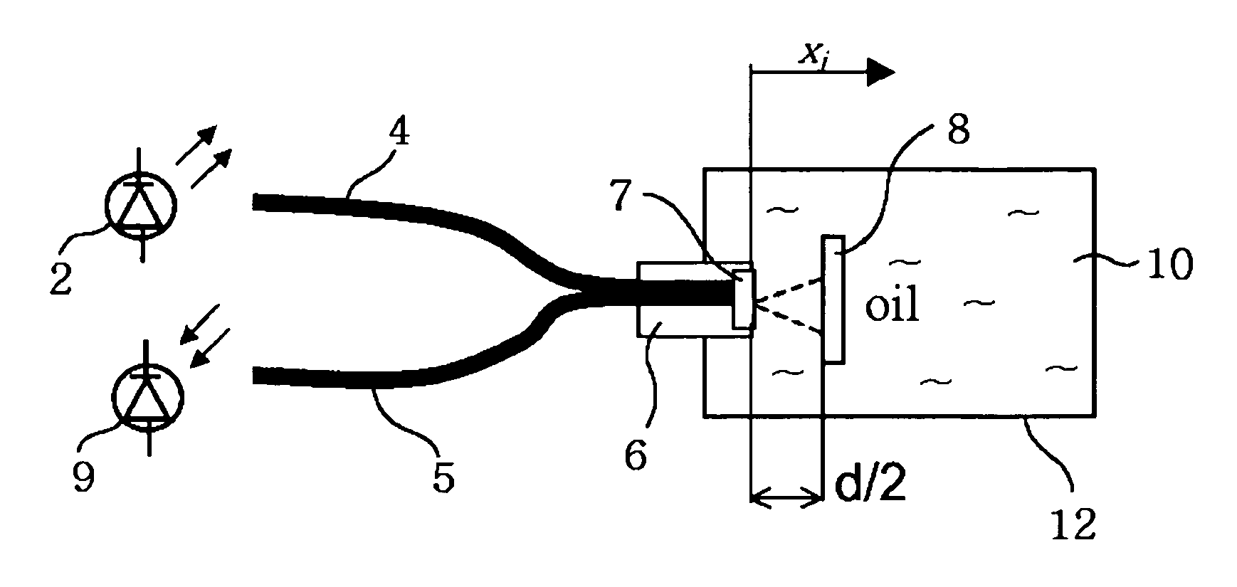
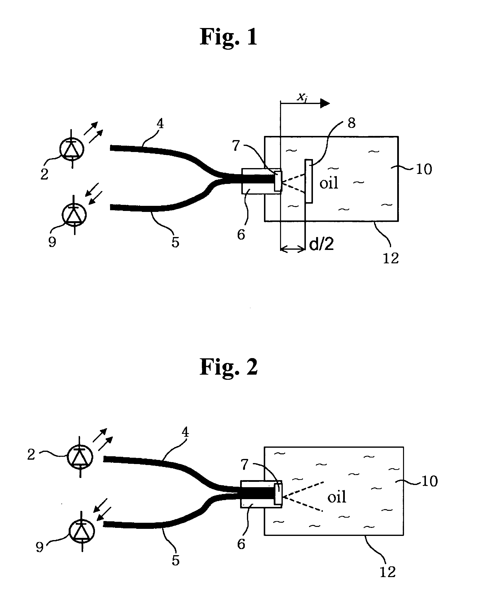
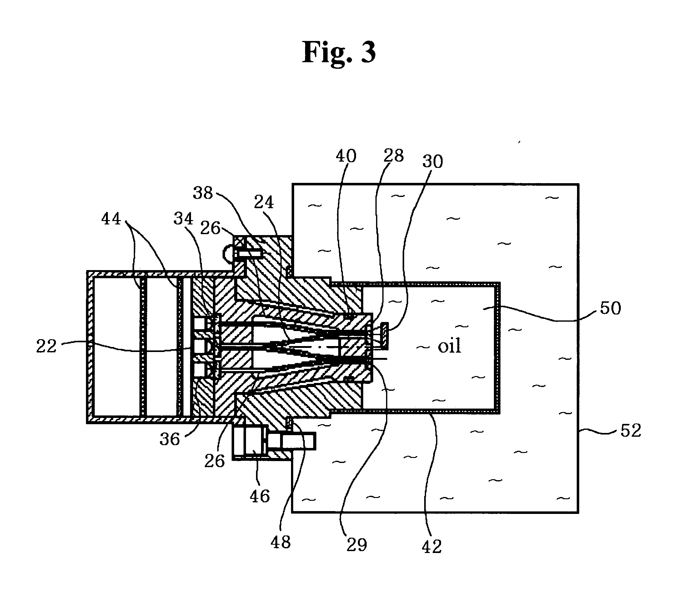
[0028] It will be readily understood that the components and steps of the present invention, as generally described and illustrated in the Figures herein and accompanying text, could be arranged and designed in a wide variety of different configurations while still utilizing the inventive concept. Thus, the following more detailed description of the preferred embodiments of the system and method of the present invention, as represented in FIGS. 1 through 5 and accompanying text, is not intended to limit the scope of the invention, as claimed, but it is merely representative of the presently preferred embodiments of the invention. The presently preferred embodiments of the invention will be best understood by reference to the drawings, wherein like parts or steps are designated by like numerals throughout.

[0029] When light passes through a medium, such as oil and the like, a certain amount of light is absorbed by the molecules of the medium and dispersed. This attenuation phenomenon...


PUM

PropertyMeasurementUnit
dielectric constantaaaaaaaaaa
dielectric constantsaaaaaaaaaa

Abstract

An apparatus for measuring oil oxidation is capable of being mounted to mechanical devices for detecting power of fluorescent light reflected from oil in real time as an indication of the oil oxidation. A plurality of first optical fibers are connected to a light-emitting member for introducing the light into oil at different incidence points. A plurality of light-reflecting mirrors are immersed in the oil and disposed opposite to the incidence points. The light-reflecting mirrors are located at different distances from the incidence points. A plurality of second optical fibers are connected to the incidence points, respectively. A plurality of light-receiving members are connected to the second optical fibers for receiving the light and outputting the signals corresponding to the received light. A control portion calculates a fluorescence quantum yield and a light absorption coefficient of the oil based upon the signals from the light-receiving members and compares them with the reference values pre-stored in the control portion to determine the oil oxidation.

Description

FIELD OF THE INVENTION [0001] The present invention relates to an apparatus for measuring oil oxidation, and more particularly, to an apparatus for measuring oil oxidation capable of being mounted to mechanical devices for detecting the power of fluorescent light reflected from oil in real time as an indication of the oil oxidation. BACKGROUND OF THE INVENTION [0002] Generally, the life span of oil, e.g., used in the engine of a vehicle, depends on various conditions, such as the running distance of the vehicle, operating time of the engine, driving environment, and so on. [0003] In most cases, because of physical and chemical degradations, the oil should be replaced regularly. The physical degradation of the oil is usually caused by metallic wear particles and dusts introduced into the oil from outside. These contaminants cause excessive wear on the surfaces of engine components, like cylinders, bearings, cylinder walls, and pistons, thereby deteriorating engine performance conside...

Claims


Application Information

Patent Timeline
Patent Type & Authority Applications(United States)
IPC IPC(8): G01N21/64G01N33/28
CPCG01N21/643G01N2021/6484G01N33/2805G01N21/645G01N21/64
Inventor KONG, HOSUNGHAN, HUNG-GUYOON, EUI-SUNGLYUBOV, MARKOVAMYSHIKIN, NICKOLAISEMENYUK, MIKHAIL
Owner KOREA INST OF SCI & TECH
Why Eureka
Try Eureka