
Method and apparatus for UV imaging

a technology of uv imaging and imaging apparatus, applied in the direction of optical radiation measurement, luminescent dosimeter, instruments, etc., can solve the problems of disrupting normal cell function and cell cannot be maintained viabl

Inactive Publication Date: 2006-08-24
WHITEHEAD INST FOR BIOMEDICAL RES +1
View PDF10 Cites 50 Cited by
  • Summary
  • Abstract
  • Description
  • Claims
  • Application Information

AI Technical Summary

Benefits of technology

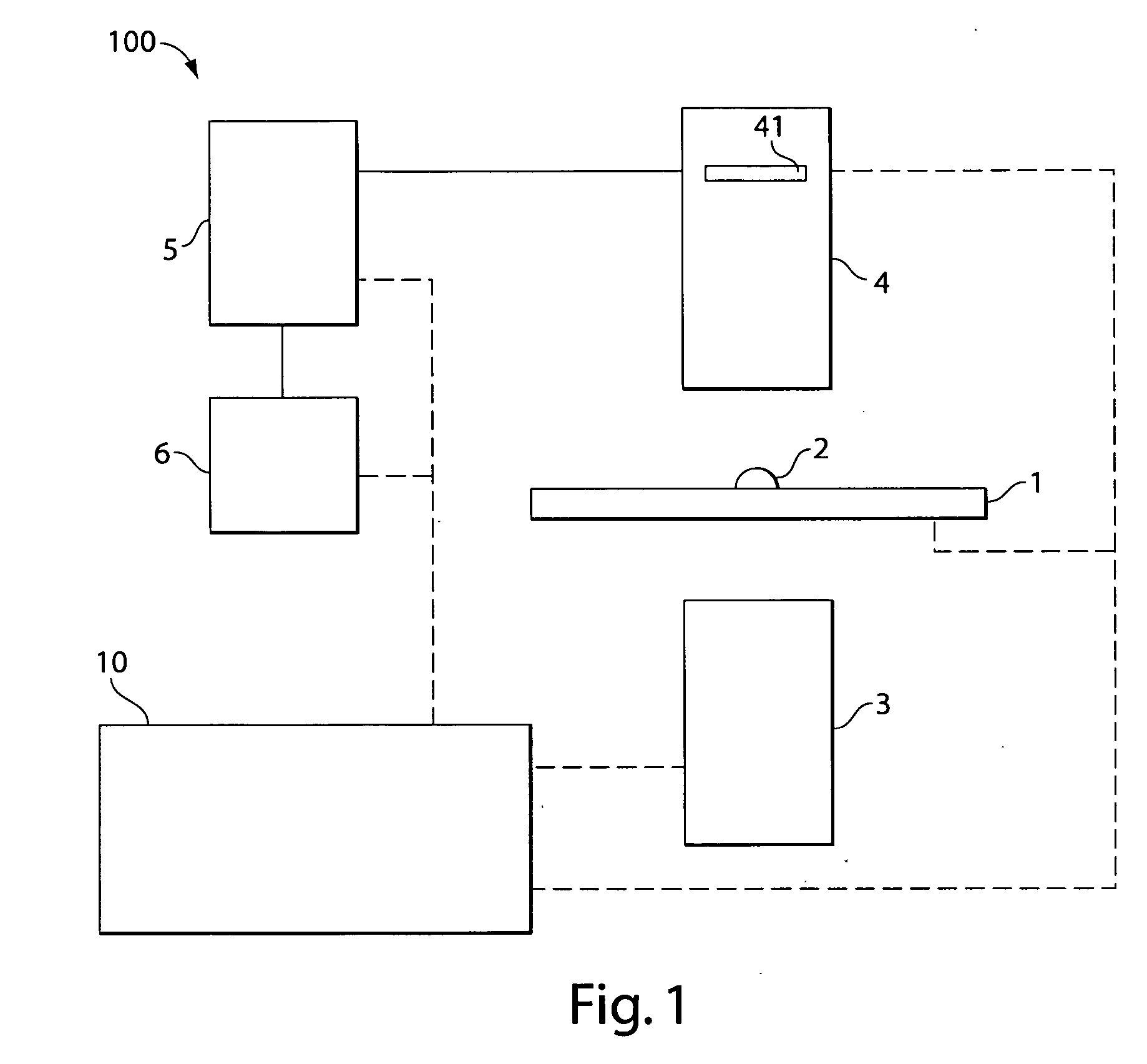
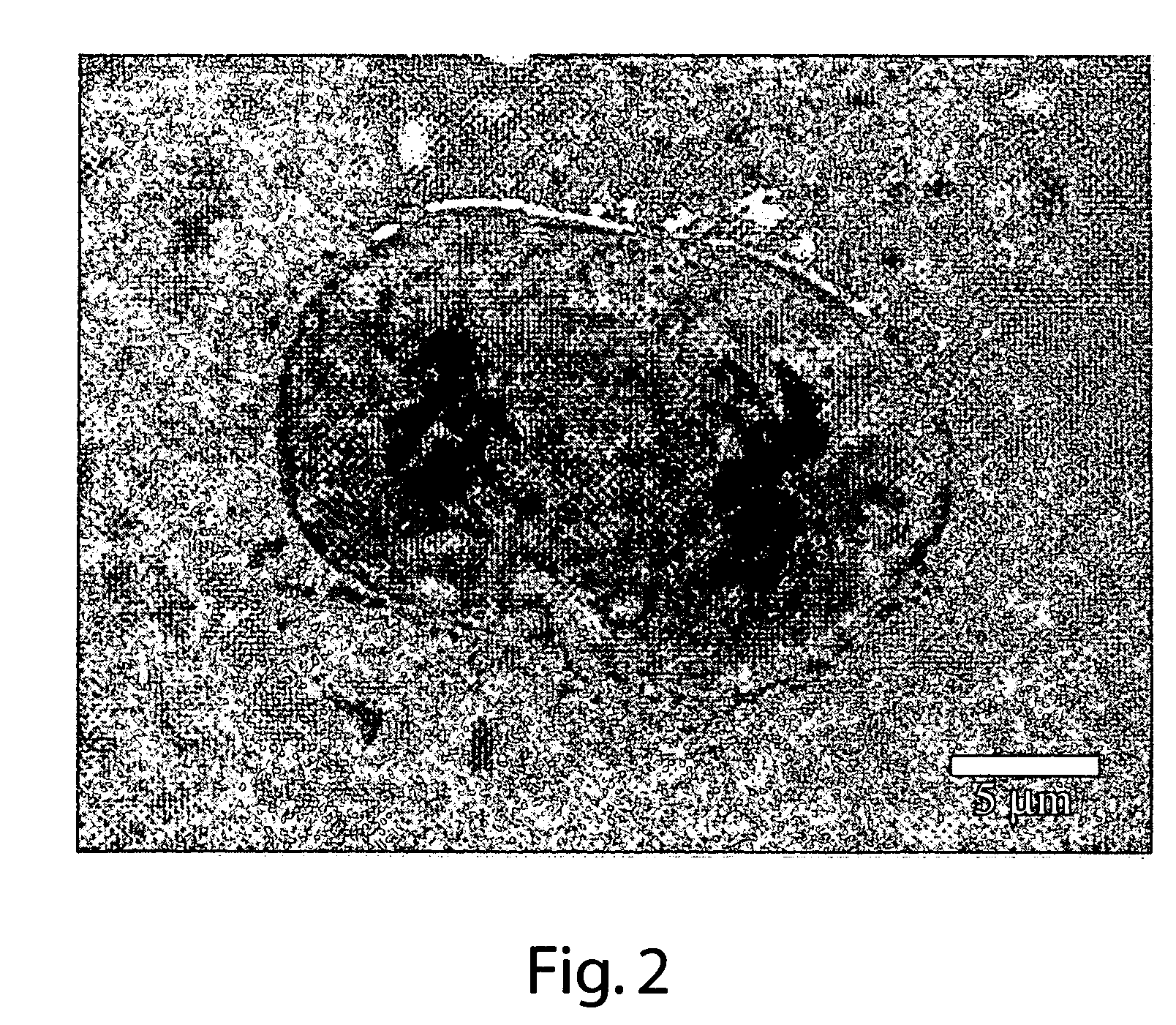
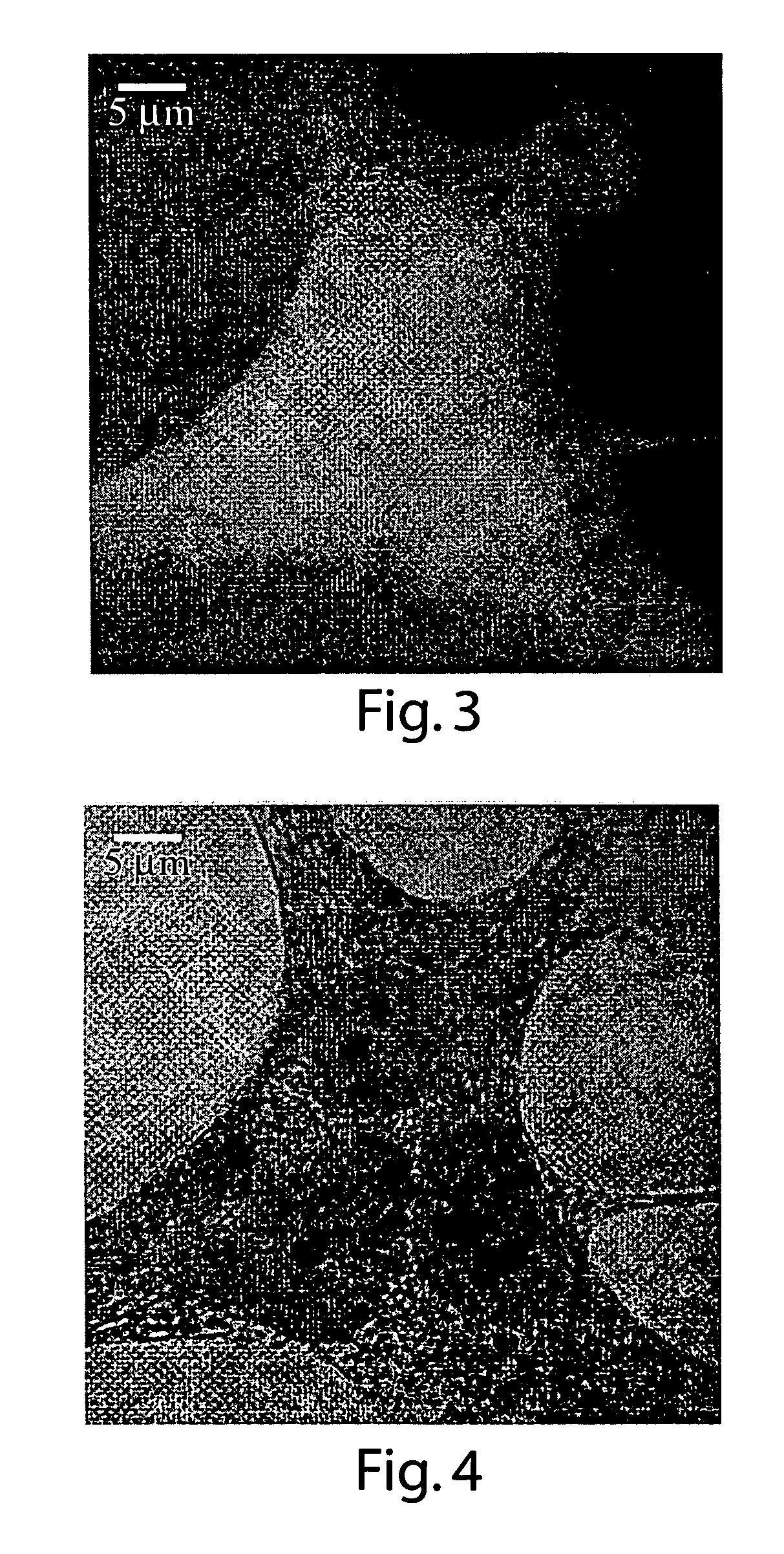
[0007] In one aspect of the invention, a method and apparatus are provided to enable imaging of a living cell or other similar subject using UV illumination and without causing necrosis or otherwise having a significant effect on functioning of the subject. For example, aspects of the invention allow for microscopy imaging of a live cell using deep UV (DUV) light, e.g., having a wavelength of about 150 nm to about 350 nm. Moreover, the cell may be repeatedly imaged under DUV conditions over a relatively long time span, such as hours, days or weeks, without causing necrosis or other detrimental effect on the cell so as to affect its normal functions during the study period. By allowing for deep UV imaging without necrosis or other significant effect on functioning, aspects of the invention provide scientists and others with the ability to view images of live subjects under illumination conditions that were previously unavailable to them.

Problems solved by technology

In general, ultraviolet (UV) light is not used in microscopy to image live cells or other living subjects because the UV illumination may cause death of the living subjects during imaging.
For example, the UV illumination may cause damage to nucleic acid or other compounds in the cell such that normal cell function is disrupted to the point that the cell can no longer remain viable.

Method used


Image

  • Method and apparatus for UV imaging
  • Method and apparatus for UV imaging
  • Method and apparatus for UV imaging

Examples


Embodiment Construction

[0031] This invention is not limited in its applications to the details of construction and the arrangement of components set forth in the following description or illustrated in the drawings. Aspects of the invention are capable of other embodiments and of being practiced or of being carried out in various ways. For example, illustrative embodiments of the invention are described below with reference to use in a microscopy device. However, it should be understood that aspects of the invention may be used in other suitable systems for any suitable application. For example, aspects of the invention relate to a method and apparatus for forming a beam for circular dichroism analysis. While this aspect of the invention is described in conjunction with 2-dimensional imaging in a microscopy device, this aspect of the invention may be used in other applications, such as spectroscopy or non-imaging applications. Similarly, aspects of the invention could be used in an endoscope for medical a...


PUM

PropertyMeasurementUnit
wavelengthaaaaaaaaaa
timeaaaaaaaaaa
time durationaaaaaaaaaa

Abstract

A method and apparatus for illuminating a subject with deep UV light and detecting 2-dimensional image information, e.g., a transmission image, fluorescence image, reflected light image, etc. The subject may be illuminated with a light pulse having a duration of 2 seconds or less and one or more components with a wavelength of between about 150 nm to about 300 nm. The light pulse may be arranged so as to minimize or eliminate any detrimental effect on the functioning of the subject, e.g., on a living cell. A concentration, mass, quantum yield, absorbance or other characteristics of one or more compounds in the subject may be determined based on one or more 2-dimensional images obtained of the subject. An illumination beam having left and right circularly polarized components may be generated, e.g., for circular dichroism analysis of a subject.

Description

[0001] This application claims priority to U.S. Applications 60 / 643,736, filed Jan. 13, 2005, 60 / 663,171, filed Mar. 18, 2005, 60 / 678,458, filed May 5, 2005, and 60 / 723,656, filed Oct. 4, 2005, which are hereby incorporated by reference in their entirety.BACKGROUND [0002] 1. Field of Invention [0003] This invention relates to methods and apparatus for imaging, such as that used in microscopy. [0004] 2. Related Art [0005] Imaging is widely used in the study of relatively small subjects, such as living cells and biological tissue. Using a microscopy device, much can be learned by viewing a cell or other material under high magnification. Often, the cell or other subject may be treated with a stain or other compounds to help identify particular features. Different illumination conditions are also used to more clearly show portions of a subject. For example, a subject may be illuminated with a particular type of light to provide better contrast when using a stain. Most microscopy device...

Claims


Application Information

Patent Timeline
Patent Type & Authority Applications(United States)
IPC IPC(8): C12Q1/00G06K9/00
CPCG01N15/1475G01N21/19G01N21/33G01N21/6456G01N21/6458G01N21/6486G02B21/16G01N15/1433
Inventor ZESKIND, BENJAMIN J.MATSUDAIRA, PAULEHRLICH, DANIEL
Owner WHITEHEAD INST FOR BIOMEDICAL RES
Learn More