
Integrated optical biosensor system (IOBS)

a biosensor and optical technology, applied in the field of biosensors, can solve the problems of high false positive rate, difficult operation of the device itself, and high cost, and achieve the effects of reducing the cost of assays, and improving the accuracy of assays

Inactive Publication Date: 2005-04-28
TRIAD NAT SECURITY LLC
View PDF23 Cites 46 Cited by
  • Summary
  • Abstract
  • Description
  • Claims
  • Application Information

AI Technical Summary

Problems solved by technology

Although biosensor systems are available for the detection of various bacteria, toxins, and viruses, the devices themselves can be difficult to operate, very expensive, and generally not portable.
These assays are not very sensitive or accurate, as they suffer from problems with cross reactivity, resulting in a high rate of false positives.
The operations required to use the conventional biosensor systems typically involve multiple steps that are very precise and intricate.
These processes provide opportunities for the introduction of errors and, thus, the biosensor results are prone to error.
The processes also require time to complete and may take up to a few days to yield results.
In fact, the diagnosis may arrive too late for any type of treatment to be effective.
Not only does the transportation take time, which may be very limited, but also the process of transportation may contaminate the sample.
Often, the sample itself may present a potential health hazard to those transporting it.
In some cases, it may not be possible to transport the sample to a laboratory, such as during combat or in other emergency situations.
Additionally, conventional biosensors systems often require highly trained personnel to operate them, although the above-described test strips are relatively simple to use, they suffer from certain problems.
Only very highly skilled personnel are able to perform the chemical processes involved in preparing and analyzing the samples that are required to complete the testing using these systems.
The amount of skill required limits the number of potential biosensor system operators.
In emergencies, there may be fewer personnel available to operate the equipment and perform the testing.
Therefore, the lack of trained personnel available to analyze the samples can become a bottleneck to rapid turnaround times when timely results are imperative.
Although the apparatus described in patent '611 provides a method for detecting certain biological material, the apparatus itself has not been optimized to provide a simplistic method of operation.
The apparatus described in patent '611 also fails to provide a portable optical biosensor system that may be used in the field as well as in a lab.
Finally, the components and materials used in the apparatus described in patent '611 are bulky and expensive.
Therefore, the system described in patent '611 does not provide a simple to use, portable, and inexpensive method of testing for the presence of certain biological material in a sample.

Method used


Image

  • Integrated optical biosensor system (IOBS)
  • Integrated optical biosensor system (IOBS)
  • Integrated optical biosensor system (IOBS)

Examples


Embodiment Construction

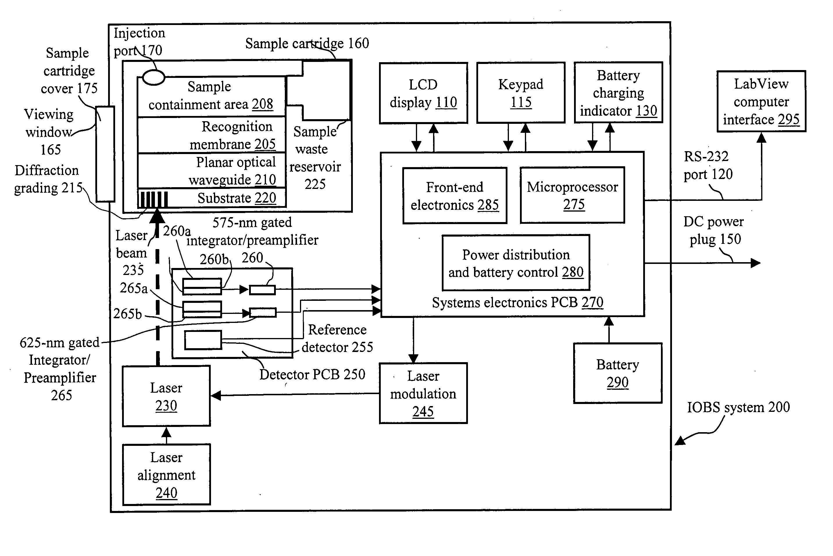
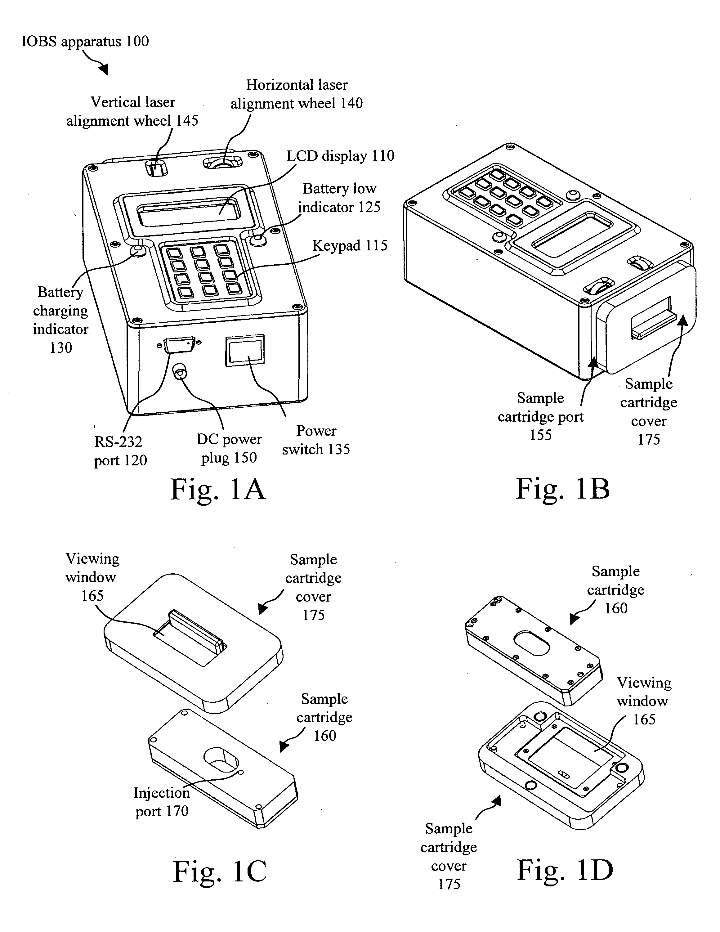
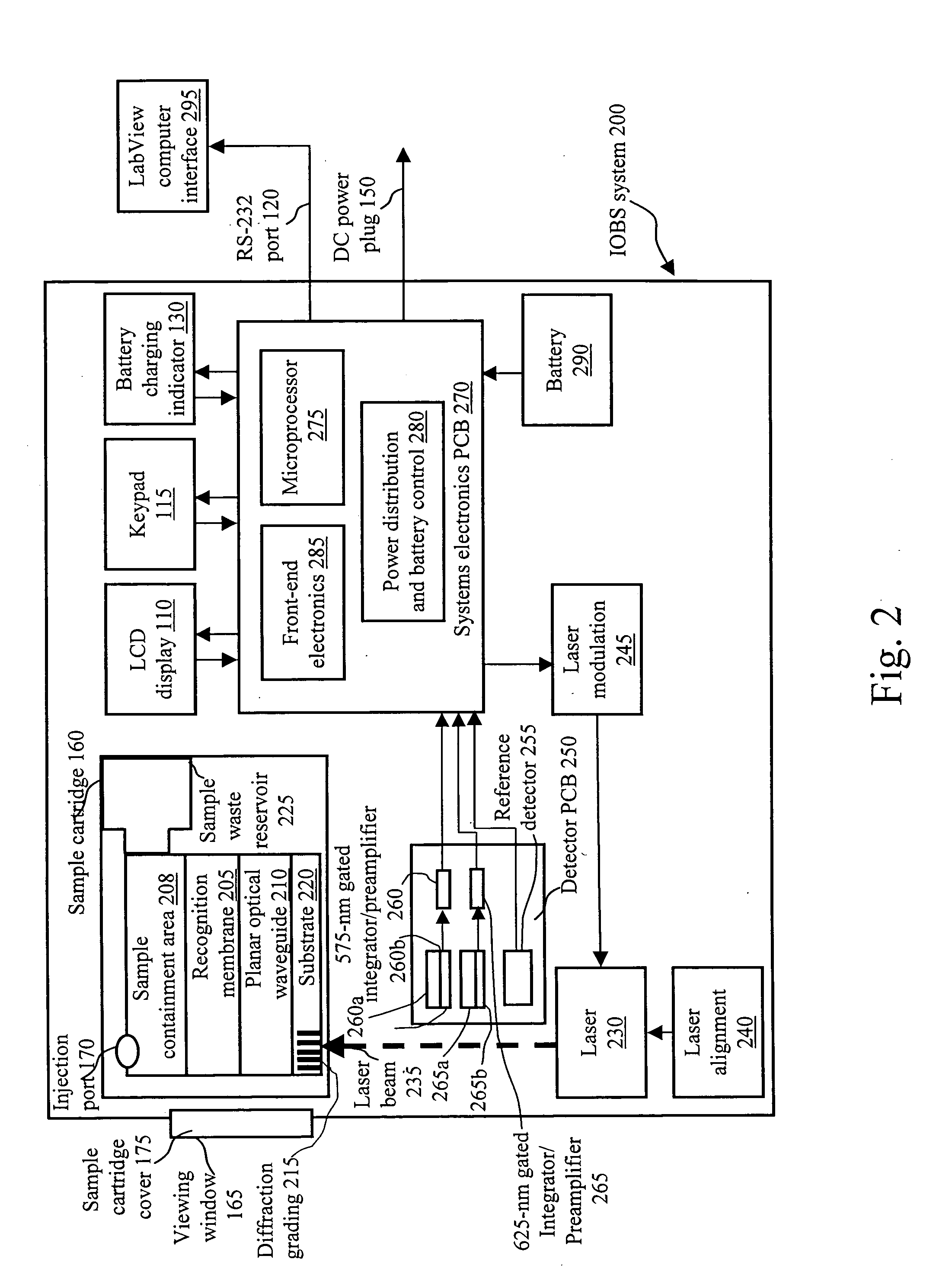
[0023] The present invention provides an apparatus for optically detecting the presence of various biological materials using simple and inexpensive components that yields accurate results quickly and with relatively little human intervention. The invention is most easily understood through reference to the drawings.

[0024]FIG. 1A shows an isometric view of an integrated optical biosensor (IOBS) apparatus 100. IOBS apparatus 100 further includes an LCD display 110, a keypad 115, a serial RS-232 port 120 for communication with a PC (not shown), a battery low indicator 125, a battery charging indicator 130, a power switch 135, a horizontal laser alignment wheel 140, a vertical laser alignment wheel 145, and a DC power plug 150.

[0025]FIG. 1B shows a top view of IOBS apparatus 100 further including a sample cartridge port 155, covered by a sample cartridge cover 175.

[0026]FIG. 1C shows a top view of a sample cartridge 160, further including an injection port 170, sample cartridge cove...


PUM

PropertyMeasurementUnit
poweraaaaaaaaaa
electricalaaaaaaaaaa
flexible lengthaaaaaaaaaa

Abstract

An optical biosensor has a first enclosure with a pathogen recognition surface, including a planar optical waveguide and grating located in the first enclosure. An aperture is in the first enclosure for insertion of sample to be investigated to a position in close proximity to the pathogen recognition surface. A laser in the first enclosure includes means for aligning and means for modulating the laser, the laser having its light output directed toward said grating. Detection means are located in the first enclosure and in optical communication with the pathogen recognition surface for detecting pathogens after interrogation by the laser light and outputting the detection. Electronic means is located in the first enclosure and receives the detection for processing the detection and outputting information on the detection, and an electrical power supply is located in the first enclosure for supplying power to the laser, the detection means and the electronic means.

Description

FIELD OF THE INVENTION [0001] The present invention relates to biosensors and more specifically to biosensors that are portable, are simple to use and operate, and cost much less than current biosensors available on the market. This invention was made with Government support under Contract No. W-7405-ENG-36 awarded by the U.S. Department of Energy. The Government has certain rights in the invention.BACKGROUND OF THE INVENTION [0002] Biosensors are devices that detect chemical or biological species with high selectivity on the basis of molecular recognition. Biosensor technology has grown rapidly over the last several years, and incorporates technological improvements in a variety of disciplines, including biochemical methodologies (e.g., organic synthesis, molecular biology) and electronics. The potential market for application of biosensor technology is enormous and includes detection and diagnostics in the health care industry and environmental monitoring. [0003] Although biosenso...

Claims


Application Information

Patent Timeline
Patent Type & Authority Applications(United States)
IPC IPC(8): G01J3/30G01N21/64G01N21/77G01N33/543
CPCB82Y10/00B82Y15/00G01N2021/6423G01N21/6428G01N33/54373B82Y30/00
Inventor GRACE, KAREN M.SWEET, MARTIN R.GOELLER, ROY M.MORRISON, LELAND JEANGRACE, WYNNE KEVINKOLAR, JEROME D.
Owner TRIAD NAT SECURITY LLC
Learn More