Handheld computer based system for collection, display and analysis of engine/vehicle data

a computer based system and engine technology, applied in computer control, testing/monitoring control systems, instruments, etc., can solve the problems of not being able to handle other data protocols, add significantly to the cost per unit, and the data port of a typical handheld computer (e.g. rs 232) is not compatible with the type of connector

Inactive Publication Date: 2005-04-28
CUMMINS INC
View PDF35 Cites 81 Cited by
  • Summary
  • Abstract
  • Description
  • Claims
  • Application Information

AI Technical Summary

Benefits of technology

[0011] The present invention is also directed to a method for creating a data pathway between (1) a data bus on an electronically controlled engine having a first electrical power source which data bus operates in accordance with a predetermined bus protocol to convey multi byte data messages of varying length and (2) a handheld computer having a second electrical power source separate from the first which operates in accordance with a data protocol which buffers received bytes of data for access by application software without keeping track of when the bytes are received thereby losing indications of the start and stop of multi byte data messages, comprising interconnecting the data bus and the handheld computer to form the data pathway external to both the data bus and the handheld computer to allow multi byte data messages of varying length to pass between the handheld computer and the data bus, intercepting the messages conveyed on the data pathway from the data bus to the handheld computer at a point external to the data bus and the handheld computer, buffering the data contained in the intercepted messages external to the data bus and the handheld computer, processing the buffered data to determine the start and stop of messages received from the data bus, adding message identifiers to the buffered data as the messages are conveyed to the handheld computer to identify the start and stop of each message, providing an electrical power source separate from the first and second power sources and performing the intercepting, buffering, processing and adding steps utilizing the electrical power source, whereby the amount of processing that the handheld computer is required to undertake for data monitoring and extraction from the data bus is reduced without employing the electrical power sources of either the handheld computer or the engine.

Problems solved by technology

The portable diagnostic device is custom built for the purposes for which it is intended which can add significantly to the cost per unit.
While these operating systems are suitable for the purposes intended, the data handling protocols established by these systems do not, without modification, handle other data protocols such as the SAE 1587 protocol.
Moreover, the data port of a typical handheld computer (e.g. RS 232) is not compatible with the type of connector normally employed on a SAE 1708 or 1939 data link system.
Accordingly, the ubiquitous nature of handheld devices, their convenience, portability, low cost make them desirable as a device for assisting in the extraction, display and upload of engine / vehicle information for transfer, e.g. via the internet, for analysis but their specialized operating system, limited storage and computing capabilities, limited battery life and their limited porting capabilities make them less than ideal.
However this system in no way suggests how to utilize a handheld computer to connect with a data link (such as a J1708 or J1939) to collect, display and upload in an efficient manner that does not require modification of the operating software that could interfere with the other functions for which the operating software of the handheld device was designed.

Method used


Image

  • Handheld computer based system for collection, display and analysis of engine/vehicle data
  • Handheld computer based system for collection, display and analysis of engine/vehicle data
  • Handheld computer based system for collection, display and analysis of engine/vehicle data

Examples


Embodiment Construction

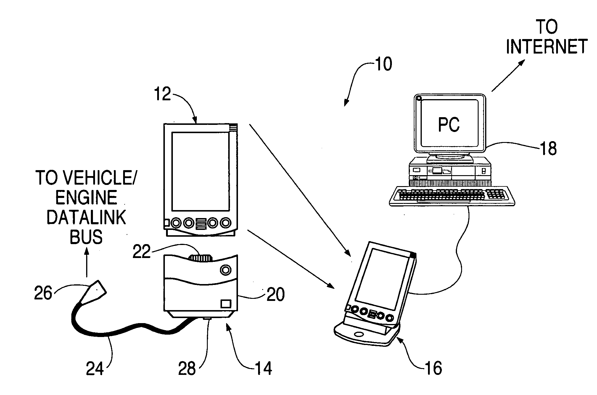
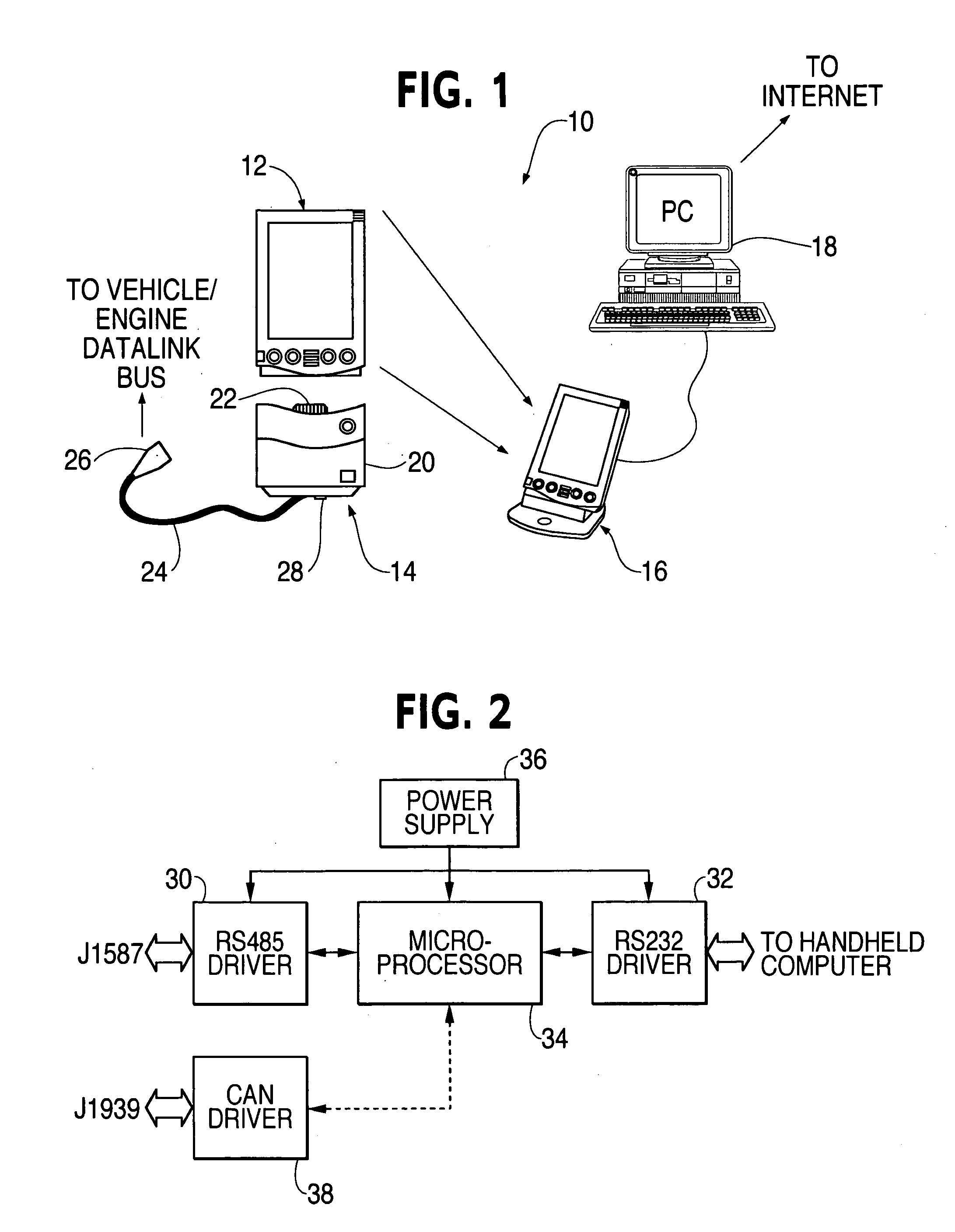
[0043] As shown in FIG. 1, the vehicle data system 10 of the present invention is defined by four primary system components: a handheld computer 12, such as a Palm Pilot® device, an adapter system 14, a handheld computer cradle 16 and a personal computer (PC) 18. In addition, there are four primary component interfaces: the adapter interface with the vehicle data bus (e.g. J1587), the adapter interface with the handheld computer, the PC interface (between the handheld computer and the PC) and the internet interface which connects the PC database to the internet. Finally, there are two user interfaces: the handheld computer user interface and the PC support utility user interface.

[0044] The handheld computer 12 and adapter 14 are portable devices that can be used to inspect and maintain remote equipment (such as at a construction site or a mining site). The collected data can then be returned to the operations center where it is uploaded to PC 18 for advanced analyses. When the PC i...


PUM


Abstract

A novel and improved engine data system for collecting, displaying and analyzing engine/vehicle data is provided. The system have advantageously results in a more effective, convenient, portable and low cost method of monitoring and processing vehicle data. The vehicle data system includes a handheld computer containing operating system software adapted to operate the handheld computer in accordance with a data protocol different from a vehicle bus protocol and a handheld microprocessor for executing the operating system software. The system importantly includes an adapter for creating a data pathway between a vehicle bus connector and an external data port provided on the handheld computer which is physically incompatible with the engine bus connector. The adapter includes a data port connector for connection with the external data port, a bus compatible connector for connection with the engine bus connector, a battery power supply separate from the power supply of the handheld compuer and an adapter microprocessor powered by the battery power supply and connected via the data pathway with the bus compatible connector for protocol conversion of the data received from the engine bus. An engine data adapter system for creating a data pathway between the engine data bus and the handheld computer while determining the start and stop of messages received from the data bus and adding message identifiers to the engine data so as to minimize the required data processing by the handheld computer.

Description

FIELD OF THE INVENTION [0001] The present invention relates to a system and method which employ a handheld computer to collect, display and upload engine / vehicle data to a personal computer for analysis. BACKGROUND OF THE INVENTION [0002] The advantages and benefits associated with extracting, displaying and analyzing data from engine powered equipment, such as vehicles, is well recognized and accepted. Fleet operators can examine the accrued data to determine service needs and improper equipment utilization. Service personnel can use the collected information to identify the cause of any failure, to aid in diagnosis, to predict future failures, to schedule maintenance / repairs, and to correct any problems before an actual failure occurs. Such diagnosis and failure prediction are particularly pertinent to automobiles, trucks and static installations of engine powered equipment, such as diesel powered electrical generators, so that minor problems can be repaired before they lead to ca...

Claims


Application Information

Patent Timeline
Patent Type & Authority Applications(United States)
IPC IPC(8): G05B15/02G05B23/02G06F13/00G06F13/36G06F19/00G07C5/00
CPCG01M17/00G07C5/008G05B23/0283
Inventor PAJAKOWSKI, ANDREW J.KRUTULIS, JON E.KNIGHT, ALEXPHILLIPS, MICHAEL W.KIMBALL, MICHAELSHIPMAN, LEE GENEBEITZINGER, JOE
Owner CUMMINS INC
Why Eureka
Try Eureka