
Tape-manufacturing system having extended operational capabilites

a manufacturing system and capability technology, applied in the direction of superconductor devices, vacuum evaporation coatings, coatings, etc., can solve the problems of short hts conductor samples fabricated at high performance levels, limited size of available ion beam sputter sources, and long production runs

Inactive Publication Date: 2005-05-05
SUPERPOWER INC
View PDF81 Cites 6 Cited by
  • Summary
  • Abstract
  • Description
  • Claims
  • Application Information

AI Technical Summary

Benefits of technology

[0009] An embodiment of the present concerns an in-process repairable e-beam deposition source. This is particularly advantageous when used in a tape-manufacturing system for coating elongated substrates as the in-process repairable e-beam deposition source permits creating coatings having integrity over the lengths required to make, for example, HTS conductor practicable, as well as maintaining the integrity on such lengths economically. To that end, the e-beam deposition source may be self-contained so as to be isolatable from the tape-manufacturing system. In this manner, the integrity of a tape substrate that is being processed in the tape-manufacturing system can be maintained, while at the same time, the e-beam deposition source is repaired.
[0010] An isolation mechanism may be provided for isolating an e-beam deposition source from the tape-manufacturing system. For example, an auxiliary chamber communicating with the tape-manufacturing system may be used to accommodate the in-process reparability of an e-beam deposition source. Such auxiliary chamber is evacuatable. The isolation mechanism may further including a closeable passage communicating with an atmosphere external to the tape-manufacturing system. The closeable passage is capable of a vacuum tight seal such as, for example, a passage able to maintain a pressure of at least about 1 torr. In this manner, an e-beam deposition source is interchangeable, thereby making the deposition source in-process repairable. Further, the auxiliary chamber may include a retractor capable of moving an e-beam deposition source into the tape-manufacturing system from the auxiliary chamber and back out of the tape-manufacturing system.
[0011] Alternatively, the self-contained e-beam deposition source may further include a redundant filament structure. Again, it may be desirable to provide an isolation mechanism for isolating an e-beam deposition source from the tape-manufacturing system. The filament structure includes at least two filaments and may include up to six filaments. Applicant believes that a redundant filament structure including four filaments would work effectively. The self-contained e-beam deposition source may further include a filament alignment mechanism for aligning an emitting portion of the filament structure with a directing structure of the e-beam deposition source. Such filament alignment mechanism may be particularly beneficial when replacing a spent filament with a replacement filament.
[0014] As noted, the tape-manufacturing system may include a controller that communicates with the at least two e-beam deposition sources and the at least one assist source. The tape-manufacturing system may further include at least one sensor in communication with the controller. Examples of the at least one sensor includes any one of a flow meter, a species monitor (e.g., an ion current monitor [e.g., a Faraday cup]), a filament state monitor, a deposition sensor, a temperature sensor, a pressure sensor, a vacuum sensor, a speed monitor, and combinations thereof. The controller at least regulates the at least two e-beam deposition sources. Also, the controller may regulate the at least one assist source. In addition, the controller may regulate a translational speed of the tape substrate by communicating with a translation mechanism for moving the at least one tape substrate when included with the tape-manufacturing system.
[0020] In an embodiment, the tape-manufacturing system includes at least two assist sources, each being capable of providing a beam of a species to the coating. As with the e-beam sources, the at least two assist sources may be arrange parallelly, serially and, when a plurality are used, parallelly and serially. When arranged parallelly, the assist sources are spaced so that a species density profile of the assist source at the surface of the tape substrate matches an evaporant material flux profile of the at least two e-beam deposition sources at the surface of the tape substrate so as to effect a change to the coating. With parallelly arranged assist sources, it may be desirable to further include a spacer juxtaposed with respect to the assist sources, so as to minimize or prevent an overlap of the beam of species provided from one assist source with the beam of species provided from another assist source at the surface of the tape substrate. The at least two parallelly arranged assist sources may possess mirror symmetry with respect to a longitudinal axis of the at least one tape substrate being coated.

Problems solved by technology

This is a fundamental advance in wire technology; however, to date, only short HTS conductor samples have been fabricated at high performance levels.
A major disadvantage of such an IBAD system used for manufacturing an HTS conductor is that the size of available ion beam sputter sources are limited to about 0.6 m. In order to manufacture a conductor having lengths exceeding meters, kilometers, and even hundreds of kilometers, long production runs would be needed.
Another disadvantage with using an ion beam sputtering system is that deposition rates are limited to about 1 angstrom per second (Å / s).
An alternative might be an IBAD system relying on an electron beam (e-beam) to vaporize an evaporant material; however, this solution is limited to short production runs.
The lifetime is especially limited in an environment with gasses such as, for example, oxygen, that oxidize or corrode the filament.

Method used


Image

  • Tape-manufacturing system having extended operational capabilites
  • Tape-manufacturing system having extended operational capabilites
  • Tape-manufacturing system having extended operational capabilites

Examples


Embodiment Construction

[0039] In the following description, like reference characters designate like or corresponding parts throughout the several views shown in the figures. It is also understood that terms such as “top,”“bottom,”“outward,”“inward,” and the like are words of convenience and are not to be construed as limiting terms.

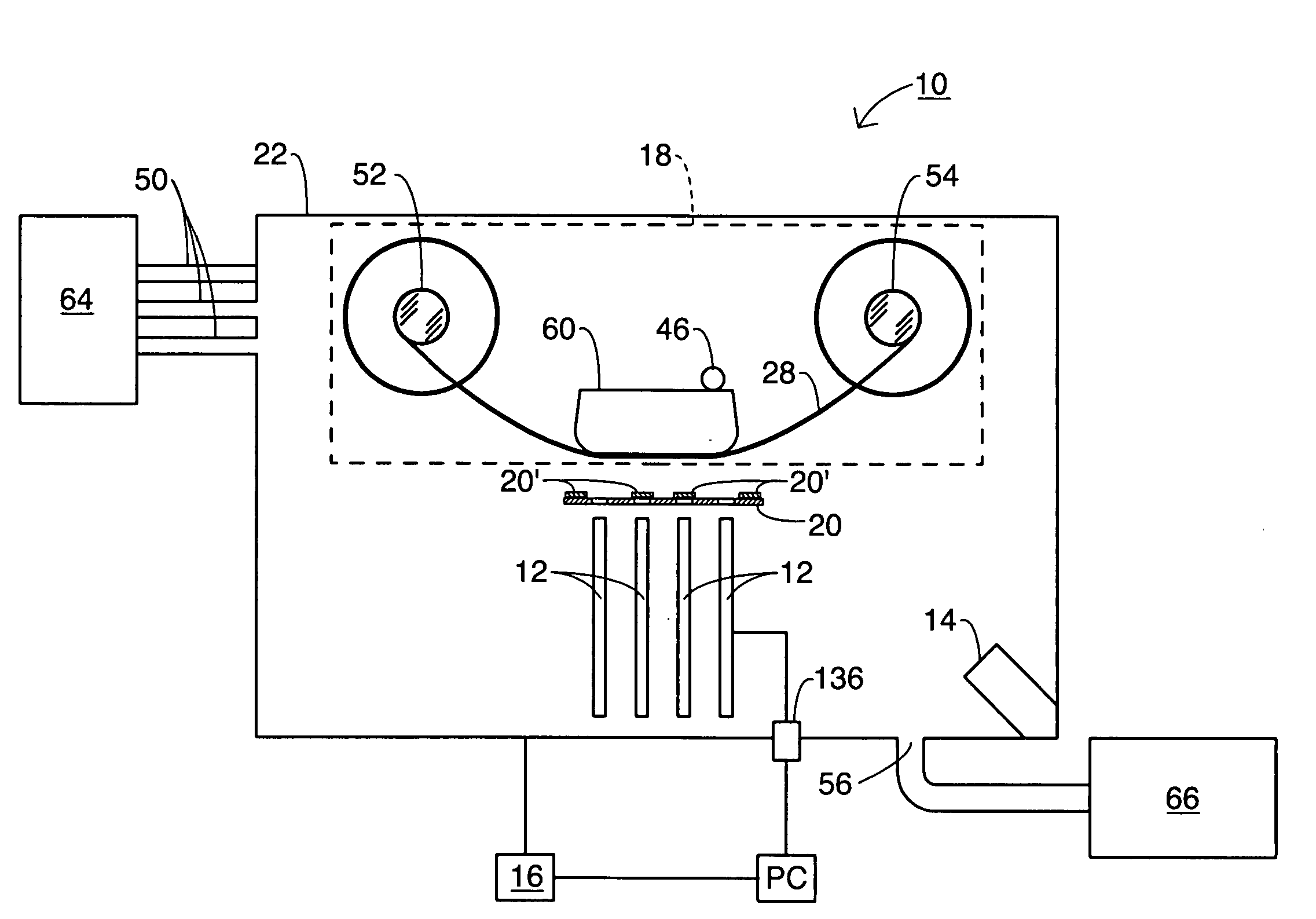
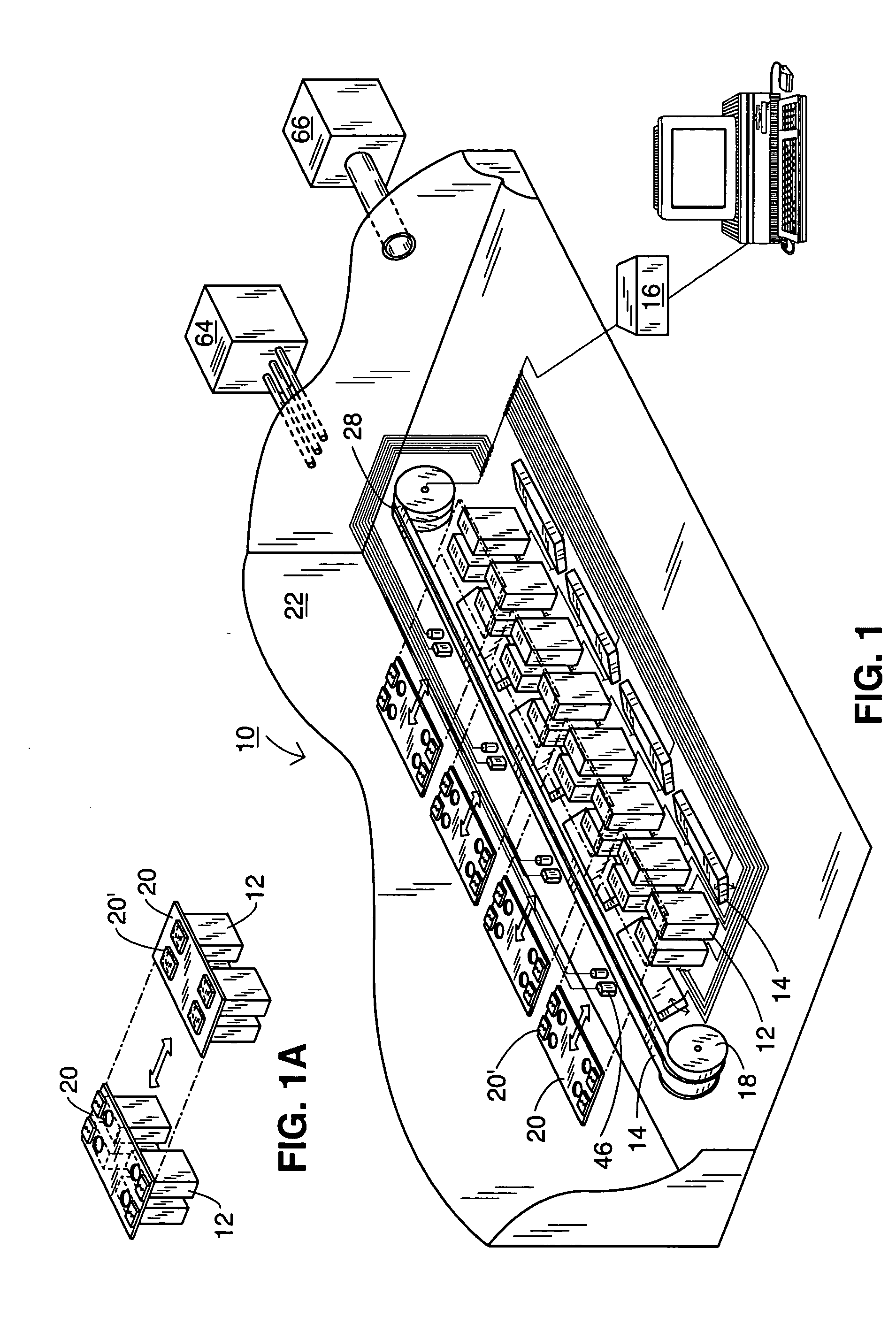
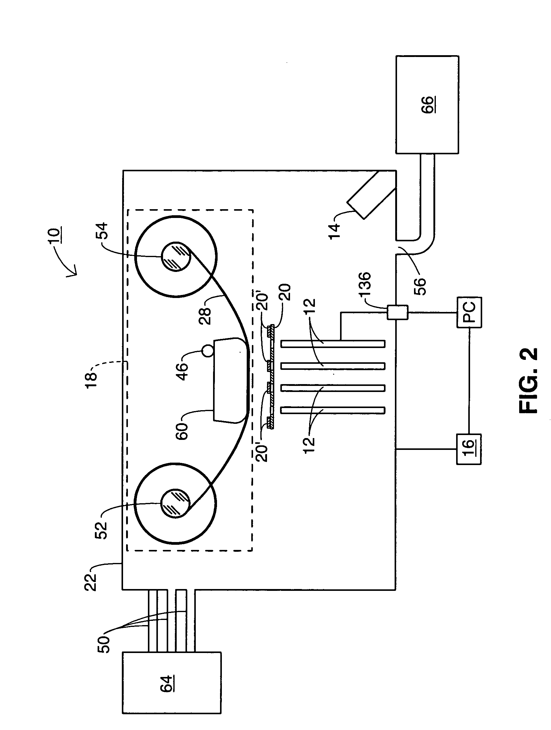
[0040] Referring to the drawings in general and to FIGS. 1 and 2 in particular, it will be understood that the illustrations are for the purpose of describing preferred embodiments of the invention and are not intended to limit the invention thereto. In FIG. 1, an isometric schematic of a tape-manufacturing system 10 according to the present invention is depicted. In FIG. 2, a cross-sectional schematic of a tape-manufacturing system 10 according to the present invention is depicted.

[0041] Referring now to FIGS. 1 and 2, the tape-manufacturing system 10 is capable of coating an elongate substrate or tape substrate 28 having greater lengths in less time, while at the same time...


PUM

PropertyMeasurementUnit
Lengthaaaaaaaaaa
Lengthaaaaaaaaaa
Lengthaaaaaaaaaa

Abstract

A tape-manufacturing system for coating at least one tape substrate such as, for example, for the manufacture of a high-temperature superconductor (HTS) conductor is disclosed. The tape-manufacturing system includes at least two electron beam (e-beam) deposition sources, at least one assist source and, optionally, a controller. Each e-beam deposition source may be in-process repairable. Each e-beam deposition source is capable of communicating an evaporant material with at least a portion of at least one tape substrate to deposit a coating thereon. The at least one assist source is capable of communicating a beam of a species to the coating. The controller communicates with the at least two e-beam deposition sources and the at least one assist source.

Description

[0001] The present invention relates generally to a tape-manufacturing system and, more particularly, to a tape-manufacturing system for economically coating a tape substrate to manufacture, for example, a textured coating on the tape substrate. BACKGROUND OF INVENTION [0002] The discovery of ceramic-based high-temperature superconductor (HTS) materials during the 1980's opened the possibility of applying superconducting technology to electric power devices such as transmission cable, transformers, motors, and generators. The ‘high’ in HTS refers to the ability to achieve the superconducting state at temperatures attainable using inexpensive liquid nitrogen, rather than the liquid helium required by the ‘low’ temperature superconductors (LTS). Nitrogen gas, when cooled, condenses at −195.8° C. (77.36 K) and freezes at −209.86° C. (63.17 K), while helium gas condenses at −268.93° C. (4.2 K) and does not freeze at atmospheric pressure. [0003] Due to superconductivity, an HTS conductor...

Claims


Application Information

Patent Timeline
IPC IPC(8): C23C14/08C23C14/22C23C14/30C23C14/54C23C14/56H01L39/24
CPCC23C14/087C23C14/22H01L39/2432C23C14/54C23C14/562C23C14/30H10N60/0381
Inventor SELVAMANICKAM, VENKAT
Owner SUPERPOWER INC
Learn More