Injection control system of internal combustion engine

Active Publication Date: 2005-05-05
DENSO CORP
View PDF22 Cites 15 Cited by
  • Summary
  • Abstract
  • Description
  • Claims
  • Application Information

AI Technical Summary

Benefits of technology

[0017] Thus, when the single injection is performed, the rotation speed fluctuation δc of the engine caused by the compression stroke in the next cylinder is estimated, and the influence of the rotation speed

Problems solved by technology

It is because all of the energy generated by combusting the injected fuel has not yet contribute to the rotation of the crankshaft.
As a result, there is a problem that the quantity of the actually injected fuel (or the torque Ti gene

Method used


Image

  • Injection control system of internal combustion engine
  • Injection control system of internal combustion engine
  • Injection control system of internal combustion engine

Examples


Example

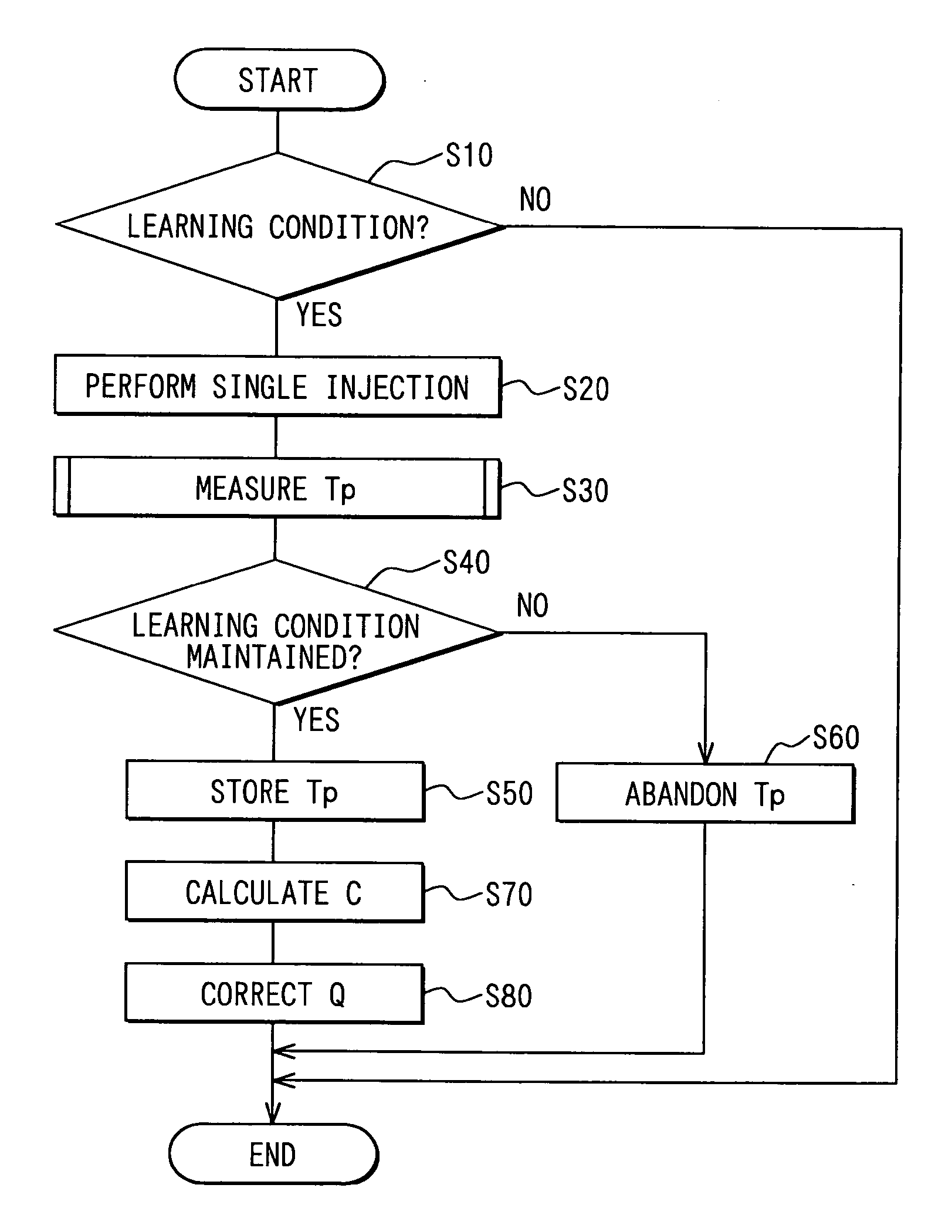
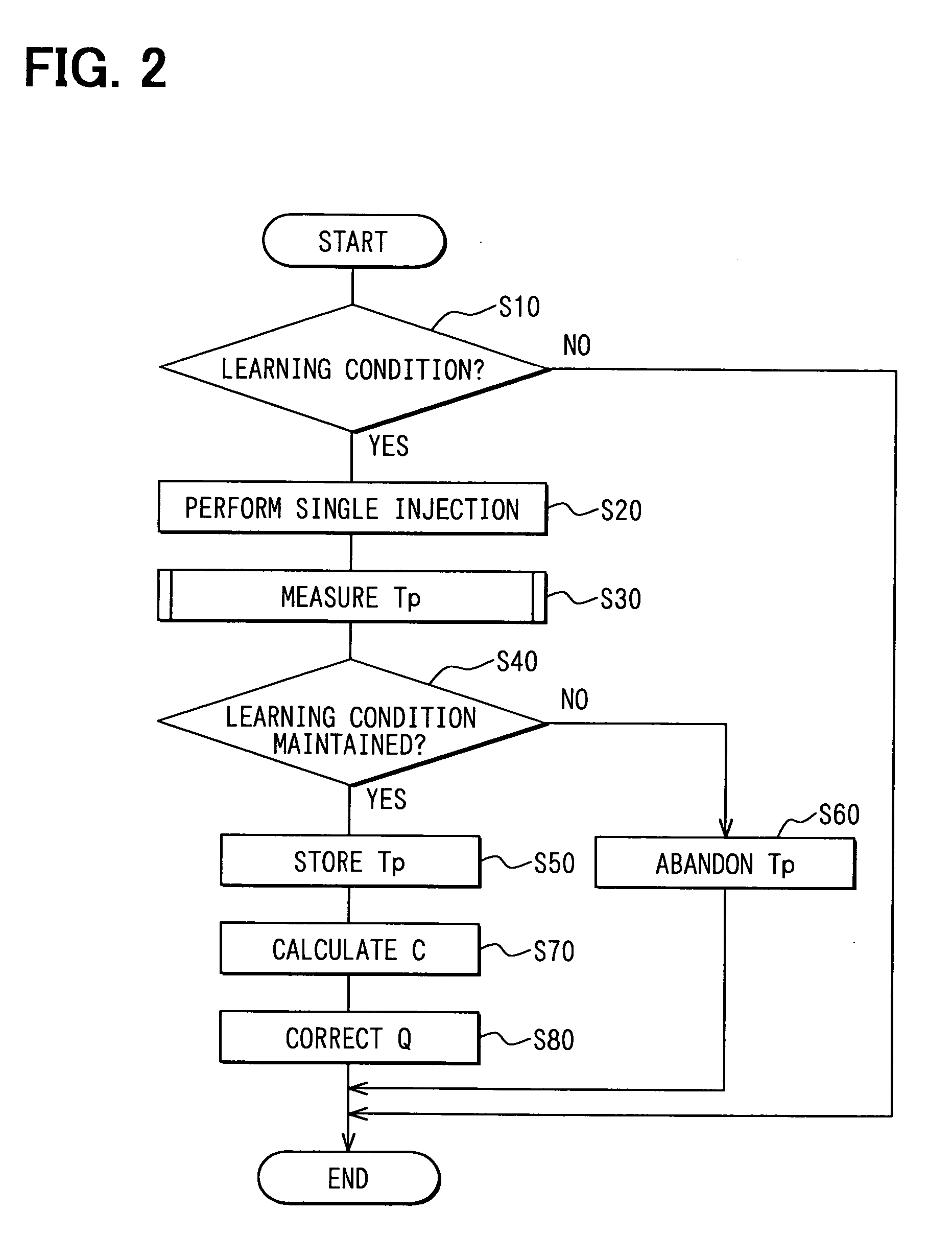
[0025] (First Embodiment)

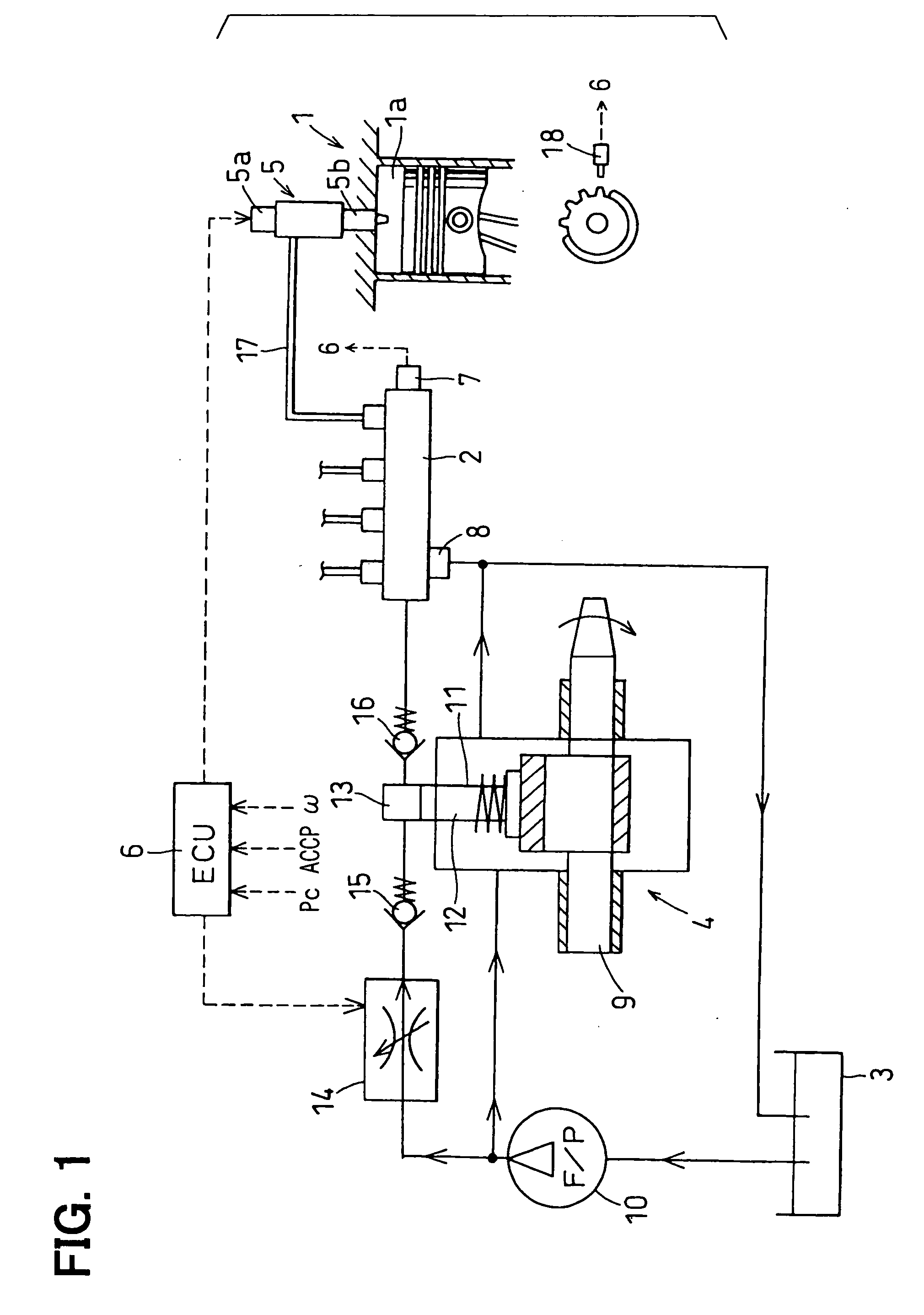
[0026] Referring to FIG. 1, a control system of an internal combustion engine according to a first embodiment of the present invention is illustrated. The engine of the present embodiment is a four-cylinder diesel engine 1 and has an accumulation type fuel injection system.

[0027] As shown in FIG. 1, the fuel injection system includes a common rail 2, a fuel pump 4, injectors 5 and an electronic control unit (ECU) 6. The common rail 2 accumulates high-pressure fuel. The fuel pump 4 pressurizes fuel, which is drawn from a fuel tank 3, and supplies the fuel to the common rail 2. The injectors 5 inject the high-pressure fuel, which is supplied from the common rail 2, into cylinders (combustion chambers 1a) of the engine 1. The ECU 6 electronically controls the system.

[0028] The ECU 6 sets a target value of a rail pressure PC of the common rail 2 (a pressure of the fuel accumulated in the common rail 2). The common rail 2 accumulates the high-pressure fuel, wh...

Example

[0060] (Second Embodiment)

[0061] Next, a method of calculating the torque proportional value (the characteristic value) Tp performed by an ECU 6 according to a second embodiment of the present invention will be explained based on FIGS. 4 and 5.

[0062] First, in Step S31 of a flowchart shown in FIG. 4, the signal of the rotation speed sensor 18 is inputted and the engine rotation speed ω is measured. The engine rotation speed ω is measured in a period from the time point when the exhaust valve opens to the time point when the TDC of the next cylinder is detected, like the first embodiment.

[0063] Then, in Step S34, a rotation speed difference Δω is calculated for each cylinder from the engine rotation speeds ω, which are measured before and after the single injection respectively. In the case of the third cylinder, a difference Δω3 between the rotation speed ω3(i) and the next rotation speed ω3(i+1) is calculated as shown in FIG. 5. The single injection is performed at a time point ...


PUM


Abstract

An electronic control unit (ECU) of an injection control system of an internal combustion engine measures an engine rotation speed in a period from a time point when an exhaust valve opens to a time point when a top dead center of a next cylinder is detected after a single injection is performed. The ECU calculates a rotation speed fluctuation caused by the single injection based on the engine rotation speed. The engine rotation speed provided immediately after the single injection is measured after a cylinder pressure increased by the single injection decreases to substantially the same level as the cylinder pressure provided in the case where the single injection is not performed. Therefore, the rotation speed fluctuation corresponding to torque generated by the single injection can be measured accurately.

Description

CROSS REFERENCE TO RELATED APPLICATION [0001] This application is based on and incorporates herein by reference Japanese Patent Application No. 2003-375487 filed on Nov. 5, 2003. BACKGROUND OF THE INVENTION [0002] 1. Field of the Invention [0003] The present invention relates to an injection control system of an internal combustion engine for performing a learning operation of an injection quantity. [0004] 2. Description of Related Art [0005] A certain controlling method (an injection quantity learning operation) known as a method of controlling an injection quantity of a gasoline engine or a diesel engine estimates the injection quantity (or torque generated by injection) based on a fluctuation of an engine rotation speed, which is caused by combusting the injected fuel, to correct the injection quantity. [0006] A publicly known calculating method disclosed in U.S. Pat. No. 4667634 or Unexamined Japanese Patent Application Publication No. H07-59911 calculates the fluctuation of the...

Claims


Application Information

Patent Timeline
IPC IPC(8): F02D41/14F02D45/00F02D41/24F02D41/34F02D41/38
CPCF02D41/0097F02D41/1498F02D41/2438F02D2250/28F02D41/2467F02D2200/1012F02D41/2441
Inventor ASANO, MASAHIROTAKEMOTO, EIJI
Owner DENSO CORP
Why Eureka
Try Eureka