Substrate holder, plating apparatus, and plating method

a technology of substrate holder and plate, which is applied in the direction of coating, electrolysis components, electrolysis processes, etc., can solve the problems of increasing the size of the overall plating apparatus, affecting the quality of the finished product, so as to reduce the size

Inactive Publication Date: 2005-05-05
EBARA CORP
View PDF14 Cites 14 Cited by
  • Summary
  • Abstract
  • Description
  • Claims
  • Application Information

AI Technical Summary

Benefits of technology

[0011] It is therefore an object of the present invention to provide a substrate holder for detachably holding a substrate while reliably sealing the outer circumferential edge of the substrate, and a plating apparatus which is suitable for the production of a small lot of substrate products and can be reduced in size, and a plating method which is carried out by such a plating apparatus.
[0013] The substrate holder can hold the substrate by attracting the cover to the base with the substrate sandwiched therebetween, without turning or twisting the cover with respect to the base. Therefore, when the substrate holder holds the substrate, the cover and components combined therewith are prevented from being unduly deformed and a seal ring is also prevented from being strained with the deformation of the cover, etc. Consequently, the seal ring can fully seal the substrate.
[0014] The attracting mechanism may comprise a vacuum attracting mechanism. The vacuum attracting mechanism can produce sufficient attractive forces for attracting the cover to the base. When the vacuum attracting mechanism is inactivated, the base and the cover are disconnected from each other, easily and reliably releasing the substrate therebetween.
[0018] In the substrate holder according to the other aspect, the cover has a positioning mechanism for receiving and positioning the substrate attracted under vacuum by the base. The substrate is prevented from falling by gravity off the substrate holder by the positioning mechanism while the substrate is being positioned and held between the based and the cover.

Problems solved by technology

Upon rotation of the presser ring, the support is deformed, straining the seal ring which finds it considerably difficult to fully seal the outer circumferential edge of the substrate.
Therefore, the use of such a highly permeative plating solution makes it more difficult to completely seal the outer circumferential edge of the substrate.
As a result, the overall plating apparatus is liable to large in size.

Method used


Image

  • Substrate holder, plating apparatus, and plating method
  • Substrate holder, plating apparatus, and plating method
  • Substrate holder, plating apparatus, and plating method

Examples


Embodiment Construction

[0039] Preferred embodiment of the present invention will be described with reference to FIGS. 1 through 11.

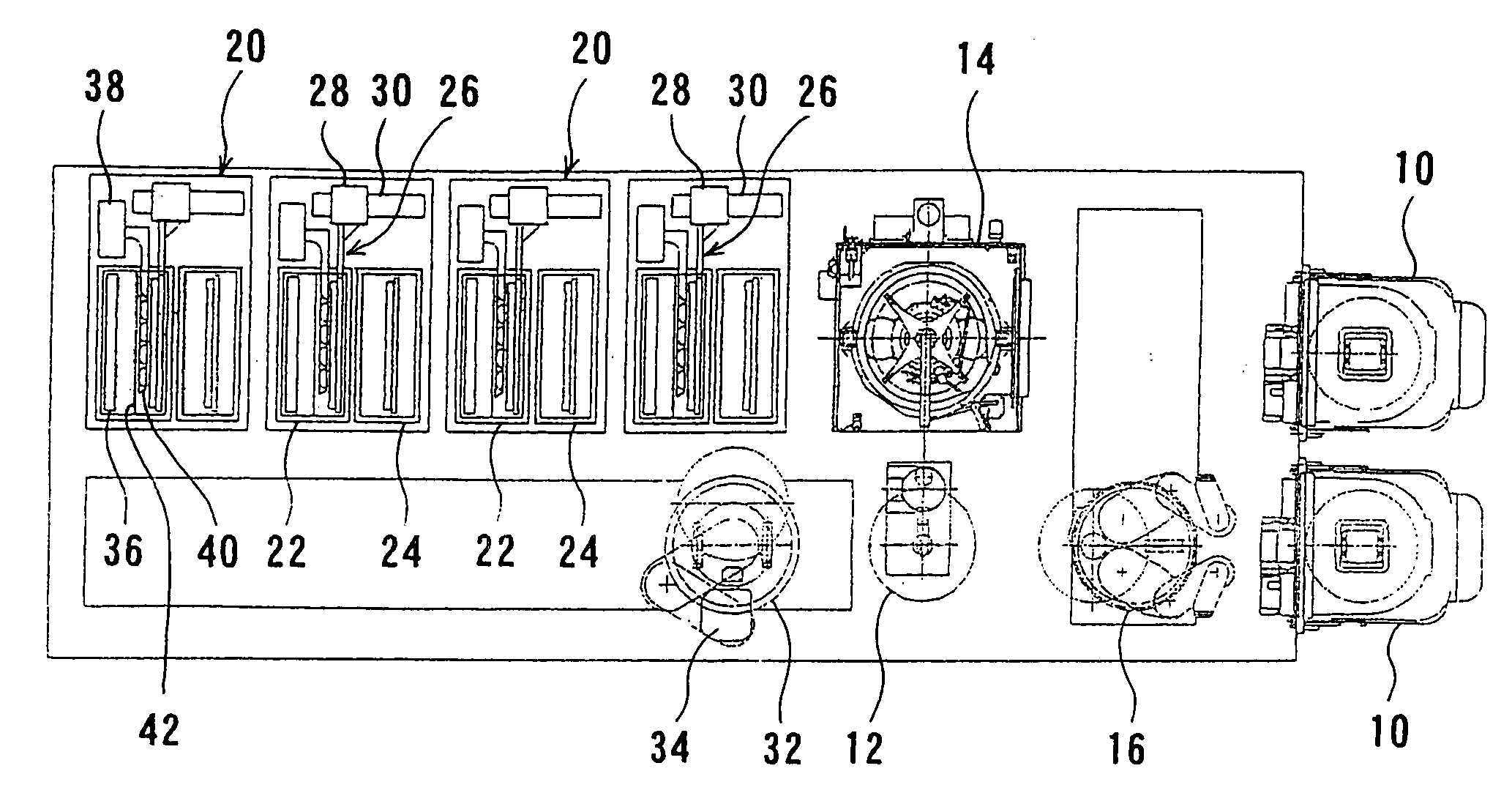
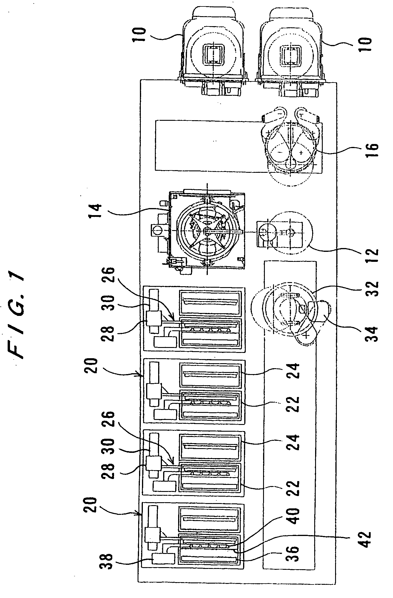
[0040]FIG. 1 shows an overall layout of components of a plating apparatus according to an embodiment of the present invention. As shown in FIG. 1, the plating apparatus has two cassette tables 10 for placing thereon respective cassettes which accommodate substrates, such as semiconductor wafers or the like, therein, an aligner 12 for aligning an orientation flat or notch of a substrate with a predetermined direction, and a rinser drier 14 for rinsing a plated substrate and rotating the rinsed plated substrate at a high speed to dry the substrate. The cassette tables 10 serve as a loading / unloading station for loading and unloading substrates. The plating apparatus also has a first transfer robot 16 movably disposed between the two cassette tables 10, the aligner 12, and the rinser drier 14, for transferring a substrate to and from the two cassette tables 10, the aligner 12, a...


PUM

PropertyMeasurementUnit
diameteraaaaaaaaaa
heightaaaaaaaaaa
temperatureaaaaaaaaaa

Abstract

A substrate holder holds a substrate while hermetically sealing an outer circumferential edge and a reverse side of the substrate and exposing a surface of the substrate. The substrate holder has a base and a cover having an opening defined therein and positioned to place the substrate between the base and the cover. An attracting mechanism couples the base and the cover to each other to hold the substrate between the base and the cover, with the surface of the substrate being exposed through the opening.

Description

BACKGROUND OF THE INVENTION [0001] 1. Field of the Invention [0002] The present invention relates to a substrate holder for use in a plating apparatus for plating a to-be-plated surface of a substrate, especially to form a plated film in fine trenches for interconnection, holes, and resist openings in the surface of a semiconductor wafer, or to produce bumps (protrusive electrodes) on the surface of a semiconductor wafer for electric connection to package electrodes or the like, a plating apparatus having such a substrate holder, and a plating method using such a substrate holder. [0003] 2. Description of the Related Art [0004] In a TAB (Tape Automated Bonding) and a flip chip, for example, protrusive connection electrodes (bumps) of gold, copper, solder, or nickel, or layers thereof are formed at predetermined locations (electrodes) on the surface of a semiconductor chip with interconnections formed thereon, and the semiconductor chip is electrically connected to package electrodes...

Claims


Application Information

Patent Timeline
Patent Type & Authority Applications(United States)
IPC IPC(8): C25D7/12C25D17/06C25D19/00H01L21/00H01L21/60H01L21/683H01L21/687
CPCC25D17/06H01L21/67126H01L21/68721C25D17/001H01L21/68785C25D7/123H01L21/68764
Inventor YOSHIOKA, JUNICHIROKATSUOKA, SEIJISEKIMOTO, MASAHIKOENDO, YASUHIKOGUO, YUGANG
Owner EBARA CORP
Why Eureka
Try Eureka