Method, device and system for mixing liquids

a technology of liquid mixing and mixing device, applied in the direction of liquid displacement, separation process, instruments, etc., can solve the problems of difficult control of liquid transport, inability to meet expectations, and high time consumption, so as to minimize the uneven concentration and precise mixing ratio

Inactive Publication Date: 2005-05-05
KONICA MINOLTA INC
View PDF9 Cites 39 Cited by
  • Summary
  • Abstract
  • Description
  • Claims
  • Application Information

AI Technical Summary

Benefits of technology

[0013] The present invention is directed to solve the problems pointed out above, and therefore, an object of the present invention is to mix two liquids faster at a precise mixing ratio compared to conventional methods. Another object of the present invention is to minimize unevenness of concentration in the channel width direction.
[0022] In addition, the first pump is so controlled that a slight pressure is generated in order to prevent backflow of the first liquid at a time when intermittent liquid transport of the first liquid is stopped.
[0024] The present invention enables mixing of two liquids faster at a precise mixing ratio compared to conventional cases. In addition, the present invention allows for minimization of unevenness of concentration in the channel width direction.

Problems solved by technology

In some applications, however, a problem arises of requiring a lot of time in the case of mixing by voluntary diffusion using channels having a width of 100 μm or so.
Such a problem arises, for example, when a particle diameter is large.
Further, when a reaction starts at the moment of interflow of liquids, the reaction proceeds prior to sufficient mixing, so that results in line with expectations cannot be obtained.
Such a method, however, causes channel resistance to increase, leading to the difficulty in control of liquid transport.
When a mixing ratio is far from 1:1, however, it was found that uniform mixing is difficult at an intended mixing ratio due to influences of channel walls on a liquid having a smaller mixing ratio of two liquids as shown in FIG. 14.
Additionally, even if a ratio of amount of transported liquids is an intended value, there are some problems, including a problem that unevenness of concentration easily occurs in the channel width direction and a problem that it takes a lot of time to eliminate the unevenness of concentration by voluntary diffusion to provide uniform concentration.

Method used


Image

  • Method, device and system for mixing liquids
  • Method, device and system for mixing liquids
  • Method, device and system for mixing liquids

Examples


first embodiment

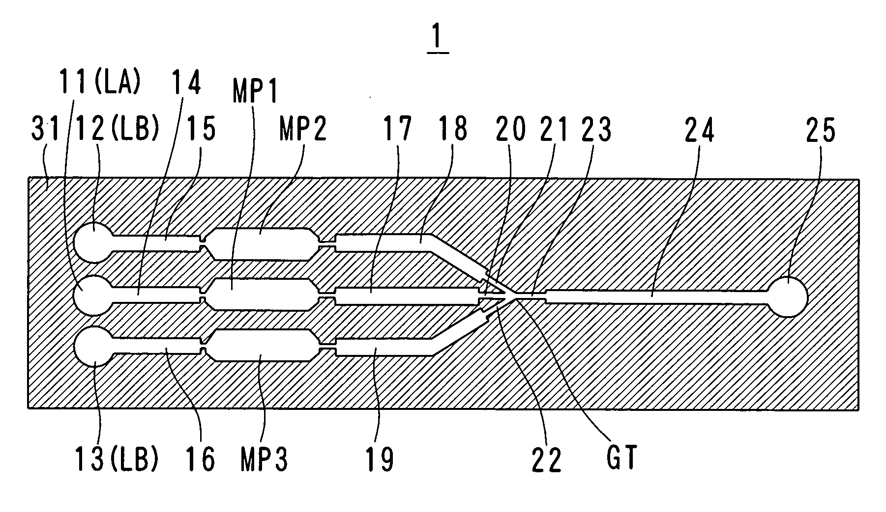
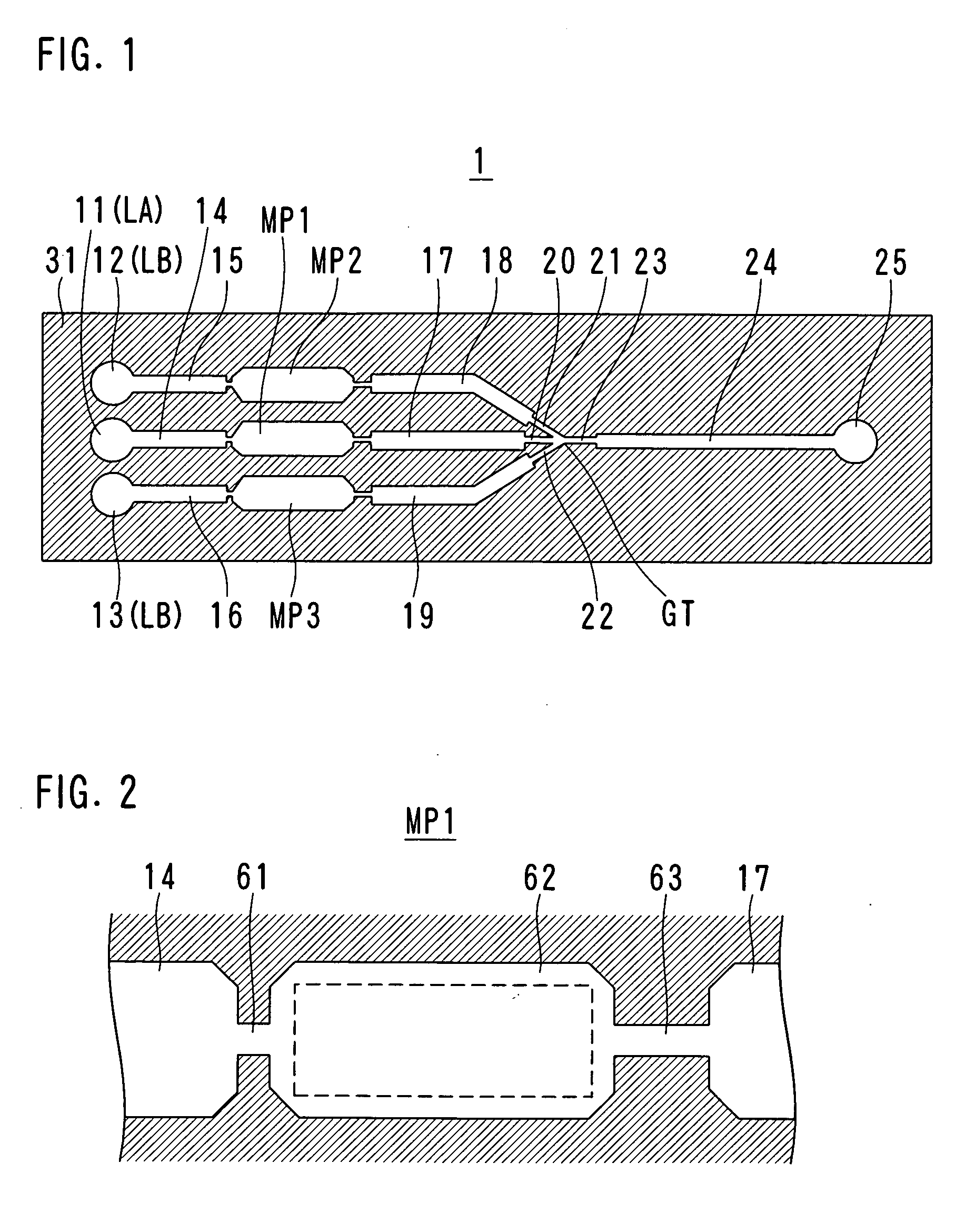
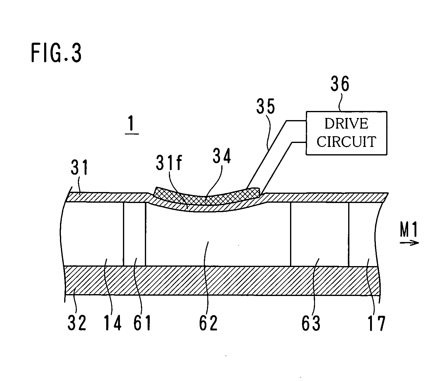
[0047]FIG. 1 is a plan view schematically showing a structure of a microfluidic system 1 that is a first embodiment of a mixing device in the present invention, FIG. 2 is a plan view of a micropump MP1 shown in FIG. 1, FIG. 3 is a front sectional view of the micropump MP1, FIGS. 4A-4H show an example of a manufacturing process of the micropump MP1, FIG. 5 is a diagram showing an example of channel resistance characteristics of openings of the micropump MP1, and FIGS. 6A and 6B as well as FIGS. 7A and 7B show examples of waveforms of a drive voltage of a piezoelectric element respectively.

[0048] Referring to FIG. 1, the microfluidic system 1 is structured on a silicon substrate 31 in the form of a microchip. The microfluidic system 1 is so structured that a liquid LA delivered by the middle micropump MP1 and a liquid LB delivered by each of micropumps MP2 and MP3 that are provided on the both sides of the micropump MP1 flow together at a confluence GT, and thereby to mix together fo...

second embodiment

[0118] In the microfluidic system 1 of the first embodiment discussed above, the micropumps MP1-MP3 are used, the number of which is equal to the number of channels 17-19 joining together at the confluence GT. Instead, in the second embodiment, one micropump MP is used to transport a liquid LB and a channel is branched, since the channels 18 and 19 joining together transport the same liquid LB.

[0119]FIG. 17 is a plan view schematically showing a structure of a microfluidic system 1B according to the second embodiment of the present invention.

[0120] As shown in FIG. 17, the microfluidic system 1B includes ports 11B and 12B, micropumps MP1 and MP2, channels 17B, 18B and 19B, narrow channels 20-23, a channel 24 and a port 25.

[0121] A liquid LA having a low mixing rate is supplied to the port 11B, while a liquid LB having a high mixing rate is supplied to the port 12B. The liquid LA is transported to the channel 17B by the micropump MP1, then to be delivered from the narrow channel 2...

third embodiment

[0140] In the embodiments discussed above, the systems are structured in which a liquid delivered from channels formed on both sides of a middle channel flow together with respect to a liquid delivered from the middle channel at the same confluence GT. It is not necessarily, however, that the liquids flow together at the same position. The liquids delivered from the both sides can interflow at separate positions. In addition, it is not required that the interflow is provided symmetrically.

[0141] In this third embodiment, a description is provided of a microfluidic system 1E in which a liquid LB delivered from both sides interflow at respective different positions.

[0142]FIG. 20 is a plan view schematically showing a structure of the microfluidic system 1E according to the third embodiment of the present invention, and FIG. 21 is a plan view schematically showing a structure of a microfluidic system 1F that is a modified example of the third embodiment.

[0143] Referring to FIG. 20, ...


PUM

PropertyMeasurementUnit
Reynolds numberaaaaaaaaaa
widthaaaaaaaaaa
thicknessaaaaaaaaaa

Abstract

A method and a device are provided which can mix two liquids faster at a precise mixing ratio. The method for mixing at least two liquids transported in respective channels includes transporting, of the two liquids, a liquid having a low mixing rate intermittently in one of the channels, and transporting, of the two liquids, a liquid having a high mixing rate so as to join the liquid having a low mixing rate from both sides of the channel for the liquid having a low mixing rate.

Description

[0001] This application is based on Japanese Patent Application No. 2003-371135 filed on Oct. 30, 2003, the contents of which are hereby incorporated by reference. BACKGROUND OF THE INVENTION [0002] 1. Field of the Invention [0003] The present invention relates to a mixing method, a mixing device and a mixing system for mixing a small amount of liquid and a small amount of another liquid in a microfluidic system or the like. [0004] 2. Description of the Related Art [0005] In recent years, a μ-TAS (Micro Total Analysis System) has drawn attention that uses a micromachining technique to microfabricate equipment for a chemical analysis or a chemical synthesis and then to perform the chemical analysis or the chemical synthesis in a microscale method. Compared to the conventional systems, a miniaturized μ-TAS has advantages in that required sample volume is small, reaction time is short, the amount of waste is small and others. The use of the μ-TAS in the medical field lessens the burden...

Claims


Application Information

Patent Timeline
Patent Type & Authority Applications(United States)
IPC IPC(8): B01F3/08G01N37/00B01F5/00B01F13/00B01F15/02
CPCB01F13/0071B01F13/0062Y10T137/87571B01F33/3011B01F33/3021
Inventor HIGASHINO, KUSUNOKISANDO, YASUHIROISHIDA, NOBUHISA
Owner KONICA MINOLTA INC
Why Eureka
Try Eureka