Molded motor

a molded motor and motor body technology, applied in the direction of windings, dynamo-electric components, magnetic circuit shapes/forms/construction, etc., can solve the problems of difficult to manufacture a molded motor using a straight core, and achieve the effect of improving the characteristics of the motor, shortening the distance between the winding and the bracket, and reducing the thickness of the motor

Active Publication Date: 2005-05-05
NIDEC SHIBAURA CORP
View PDF11 Cites 34 Cited by
  • Summary
  • Abstract
  • Description
  • Claims
  • Application Information

AI Technical Summary

Benefits of technology

[0021] The invention according to claim 3 eliminates the necessity for a motor frame, since the molding resin forms a motor frame, and thereby eliminates the necessity for one bracket. The elimination of the necessity for one bracket makes it possible to shorten the distance between the winding and the bracket and thereby reduce the thickness of the motor.
[0022] The resin molding based on the inside diameter makes it possible to achieve coincidence between the inside diameter of the stator core and the longitudinal axes of the housing and socket portion and thereby improve the characteristics of the motor.
[0023] The motor frame formed from the resin enables the motor...

Problems solved by technology

As a matter of fact, however, the manufacture of a molded motor using ...

Method used


Image

  • Molded motor
  • Molded motor
  • Molded motor

Examples


second embodiment

(Second Embodiment)

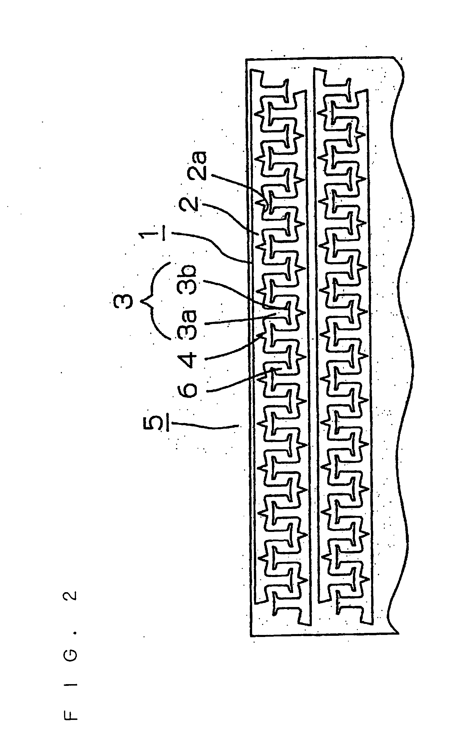
[0090] A second embodiment of the invention relating to the joined ends of the back yokes 2 of the stator 10 will now be described with reference to FIGS. 9 and 10.

[0091] In the event that the joined ends of the back yokes 2 are flat and are welded at their outer periphery alone as according to the first embodiment of the invention, the back yokes in the vicinity of their joined ends are likely to resonate with a diametrically occurring electromagnetic vibration and cause undulation about the welded joint. This problem is overcome by crank-shaped joined ends 44 according to the second embodiment of the invention.

[0092]FIG. 9 is an enlarged front elevational view of the joined ends 44 of a back yoke 2 according to the embodiment under description and their vicinity, and FIG. 10 is an enlarged front elevational view of the joined ends 44 of the back yoke 2 having a gap formed therebetween and their vicinity.

[0093] A stator 10 is made by bending a straight core 16...


PUM

PropertyMeasurementUnit
Moldableaaaaaaaaaa
aaaaaaaaaa

Abstract

In a molded motor having a motor frame molded by covering a stator composed by a straight core with a molding resin, the straight core has a stack of laminas each having a plurality of tees projecting from one long side of a belt-shaped back yoke and a V-shaped cut formed between every two adjoining tees along the back yoke and on its side from which the tees project. The straight core has an insulating layer formed by pre-molding from an insulating resin on its portions excluding at least the inner periphery of each tee. The straight core also has a winding formed about each tee having the insulating layer formed thereon. The stator is formed by bending the straight core at the cuts into an arcuate or annular shape, and joining the opposite ends of the back yokes to each other by welding or adhesion.

Description

FIELD OF THE INVENTION [0001] This invention relates to a molded motor. BACKGROUND OF THE INVENTION [0002] A stator for a molded motor is made by a common method in which an annular stator core is used, or a method in which a linear stator core (usually called a straight core) is bent into an annular shape. The prior art involving a straight core is disclosed in Japanese Patent Publications JP-A-9-308143, JP-A-10-136589 and JP-A-10-271715. [0003] As a matter of fact, however, the manufacture of a molded motor using a straight core is difficult to carry out only with the art mentioned above. [0004] This invention, therefore, provides an invention which ensures the manufacture of a molded motor using a straight core. DISCLOSURE OF THE INVENTION [0005] The invention according to claim 1 is a molded motor having a motor frame molded by covering a stator composed by a straight core with a molding resin, the straight core comprising a stack of laminas each having a plurality of tees proje...

Claims


Application Information

Patent Timeline
IPC IPC(8): H02K1/14H02K3/32H02K3/52
CPCH02K1/146Y10T29/49009H02K3/522H02K1/148
Inventor TANABE, TAKESHIROUKIKUCHI, YUUSUKE
Owner NIDEC SHIBAURA CORP
Why Eureka
Try Eureka