Dynamoelectric machine
a dynamoelectric machine and output terminal technology, applied in the direction of motor/generator/converter stopper, electric generator control, dynamo-electric converter control, etc., can solve the problems of increasing the rectified ripple voltage in the rectified output terminal voltage with electric load, increasing radio noise, and driving to unpleasant sensations, so as to improve the assembly of the stator, improve the effect of electric power generation and low rectified ripple voltag
- Summary
- Abstract
- Description
- Claims
- Application Information
AI Technical Summary
Benefits of technology
Problems solved by technology
Method used
Image
Examples
embodiment 1
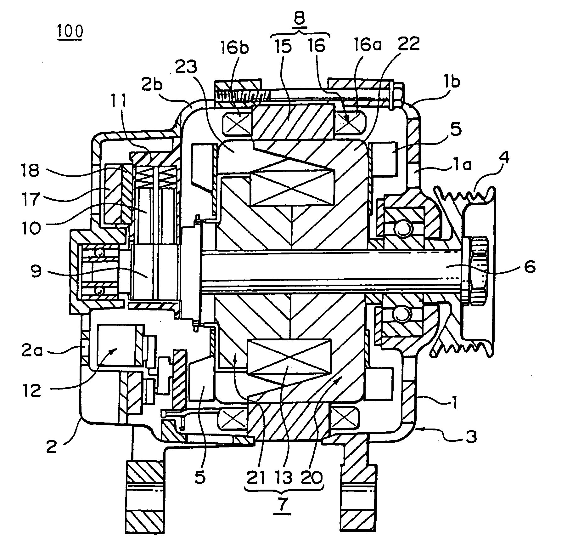
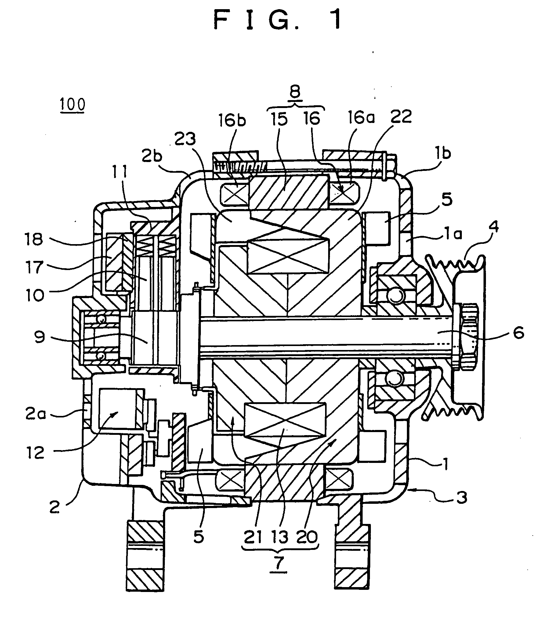
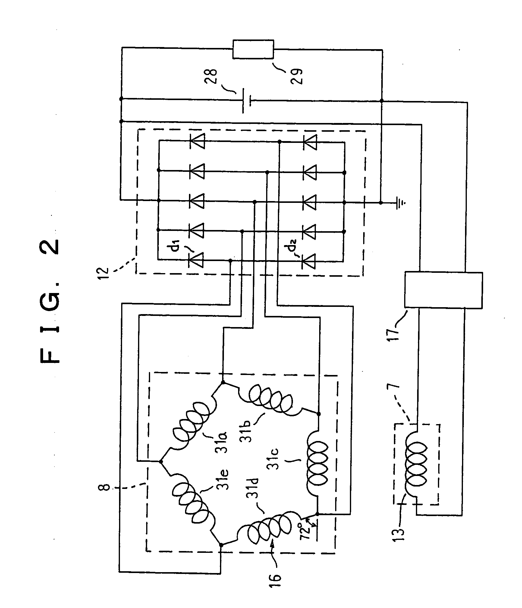
[0037]FIG. 1 is a longitudinal section showing a construction of a dynamoelectric machine according to Embodiment 1 of the present invention, FIG. 2 is a circuit diagram of the dynamoelectric machine according to Embodiment 1 of the present invention, and FIG. 3 is a development explaining a construction of an armature winding in the dynamoelectric machine according to Embodiment 1 of the present invention.
[0038] In FIGS. 1 and 2, a dynamoelectric machine 100 operates as an alternator and is constructed by rotatably mounting a Lundell-type rotor 7 by means of a shaft 6 inside a case 3 constituted by a front bracket 1 and a rear bracket 2 made of aluminum and fixing a stator 8 to an inner wall surface of the case 3 so as to cover an outer circumferential side of the rotor 7.
[0039] The shaft 6 is rotatably supported in the front bracket 1 and the rear bracket 2. A pulley 4 is fixed to a first end of this shaft 6, enabling rotational torque from an engine to be transmitted to the sha...
embodiment 2
[0073]FIG. 9 is a development explaining a construction of an armature winding in a dynamoelectric machine according to Embodiment 2 of the present invention.
[0074] In FIG. 9, an a-phase winding phase portion 32a is constructed by winding a conducting wire 30 for eight turns so as to pass through Slot Numbers 1 and 6 of the slots 15a, then winding the conducting wire 30 for eight turns so as to pass through Slot Numbers 11 and 16 of the slots 15a.
[0075] A b-phase winding phase portion 32b is constructed by winding a conducting wire 30 for eight turns so as to pass through Slot Numbers 3 and 8 of the slots 15a, then winding the conducting wire 30 for eight turns so as to pass through Slot Numbers 13 and 18 of the slots 15a.
[0076] A c-phase winding phase portion 32c is constructed by winding a conducting wire 30 for eight turns so as to pass through Slot Numbers 5 and 10 of the slots 15a, then winding the conducting wire 30 for eight turns so as to pass through Slot Numbers 15 and ...
embodiment 3
[0083]FIG. 10 is a development explaining a construction of an armature winding in a dynamoelectric machine according to Embodiment 3 of the present invention.
[0084] In FIG. 10, an a-phase winding phase portion 33a is constructed into a four-turn wave winding in each of Slot Numbers 1, 6, 11, and 16 of the slots 15a by winding a conducting wire 30 for one lap into a wave winding so as to alternately occupy Address 1 and Address 2, then winding the conducting wire 30 for one lap into a wave winding so as to alternately occupy Address 2 and Address 1, then winding the conducting wire 30 for one lap into a wave winding so as to alternately occupy Address 3 and Address 4, and finally winding the conducting wire 30 for one lap into a wave winding so as to alternately occupy Address 4 and Address 3. Here, Addresses 1 to 4 are housing positions of the conducting wire 30 in a slot depth direction inside each of the slots 15a. In other words, the conducting wire 30 is housed in four layers ...
PUM
 Abstract
Description
Claims
Application Information
 - R&D
- Intellectual Property
- Life Sciences
- Materials
- Tech Scout
- Unparalleled Data Quality
- Higher Quality Content
- 60% Fewer Hallucinations
Browse by: Latest US Patents, China's latest patents, Technical Efficacy Thesaurus, Application Domain, Technology Topic, Popular Technical Reports.
© 2025 PatSnap. All rights reserved.Legal|Privacy policy|Modern Slavery Act Transparency Statement|Sitemap|About US| Contact US: help@patsnap.com


