Optical pickup apparatus, optical disk apparatus and optical pickup adjustment method

a technology of optical pickup and optical disk, which is applied in the direction of instruments, recording information storage, disposition/mounting of heads, etc., can solve the problems of reducing the thickness of the optical disk drive, the cost of the piezoelectric element itself is high, and the driving movement range of the focusing servo operation is restricted, so as to improve the performance of the focusing servo and reduce the voltage. , the effect of reducing the thickness

Inactive Publication Date: 2005-05-05
SONY CORP
View PDF0 Cites 7 Cited by
  • Summary
  • Abstract
  • Description
  • Claims
  • Application Information

AI Technical Summary

Benefits of technology

[0013] It is an object of the present invention to provide an optical pickup apparatus and an optical disk apparatus which can be formed in a minimized thickness while realizing improvement in focusing servo performance, reduction of the voltage and reduction of the cost.
[0014] It is another object of the present invention to provide an optical disk apparatus and an optical pickup adjustment method for the optical disk apparatus wherein a connection operation and a wiring operation of signal lines for normal operation and signal lines only for adjustment of an optical pickup can be performed appropriately and readily and besides assembly and adjustment can be performed easily without an error.
[0017] With the optical pickup apparatus and the optical disk apparatus, since the hole formed in the optical pickup base plate of the swing arm unit is closed up with the semiconductor substrate on which the integrated optical pickup unit is mounted and the transparent cover, and the integrated optical pickup unit is disposed in the closed up space formed in the hole. Consequently, reduction in thickness of the optical pickup can be anticipated. Further, the optical pickup base plate functions as a heat radiating plate, and consequently, improvement in heat radiation from the semiconductor laser can be anticipated. Further, the configuration is simple, and consequently, reduction in number of parts and in cost can be anticipated.
[0019] With the optical disk apparatus, the support spring and the suspension are provided in parallel to the optical pickup base plate on which the integrated optical pickup unit is held, and the concave lens for increasing the diversion angle of the laser beam emitted from the optical pickup is provided on the integrated optical pickup unit. Further, the collimator lens for converting the light from the concave lens into parallel light is provided on the support spring, and the floating slider in which the object lens is incorporated is provided on the suspension. Consequently, the collimator lens can be displaced freely, and the distance for correction of the focus and the acceleration in the focusing servo can be increased. Further, the configuration is simple, and consequently, reduction in number of parts and in cost can be anticipated.
[0021] With the optical disk apparatus, the wiring pattern wherein the signal lines necessary for operation of the optical pickup and the signal lines necessary only for adjustment of the optical pickup are disposed separately from each other is provided on the flexible substrate for supplying a signal to the optical pickup. Consequently, the signal lines necessary for normal operation of the optical pickup and the signal lines necessary only for adjustment of the optical pickup can be handled readily and appropriately and separately from each other. Consequently, assembly and adjustment of the optical disk apparatus are facilitated, and also an error in working can be prevented effectively.
[0023] With the optical pickup adjustment method, the signal lines provided on the flexible substrate and necessary only for adjustment of the optical pickup are used to transmit signals for adjustment to perform adjustment of the optical pickup, and the wiring pattern of the signal lines necessary only for adjustment of the optical pickup is cut after completion of the adjustment of the optical pickup, whereafter assembly of the optical disk apparatus is performed. Thus, after completion of the adjustment of the optical pickup, the signal lines only for adjustment are removed to eliminate those wiring lines which are useless for ordinary operation of the optical disk apparatus. Consequently, the number of leads from the optical pickup can be reduced and an increased space can be provided in the optical disk apparatus. Also arrangement of parts is facilitated, and facilitation in assembly and compact configuration of the apparatus can be anticipated.

Problems solved by technology

The most serious obstacle to reduction in thickness of an optical disk drive is the thickness of an optical pickup which is a key device to the optical disk drive.
However, for example, in the optical pickup shown in FIG. 17, since the movable stroke of the focus is small, the range of driving movement in the focusing servo operation is restricted.
Also the cost of the piezoelectric element itself is high.
Further, since a sufficient acceleration cannot be obtained, a focusing servo operation in a high frequency band cannot be performed.
Furthermore, the MEMS still requires a high cost as a driving element for an actuator.

Method used


Image

  • Optical pickup apparatus, optical disk apparatus and optical pickup adjustment method
  • Optical pickup apparatus, optical disk apparatus and optical pickup adjustment method
  • Optical pickup apparatus, optical disk apparatus and optical pickup adjustment method

Examples


Embodiment Construction

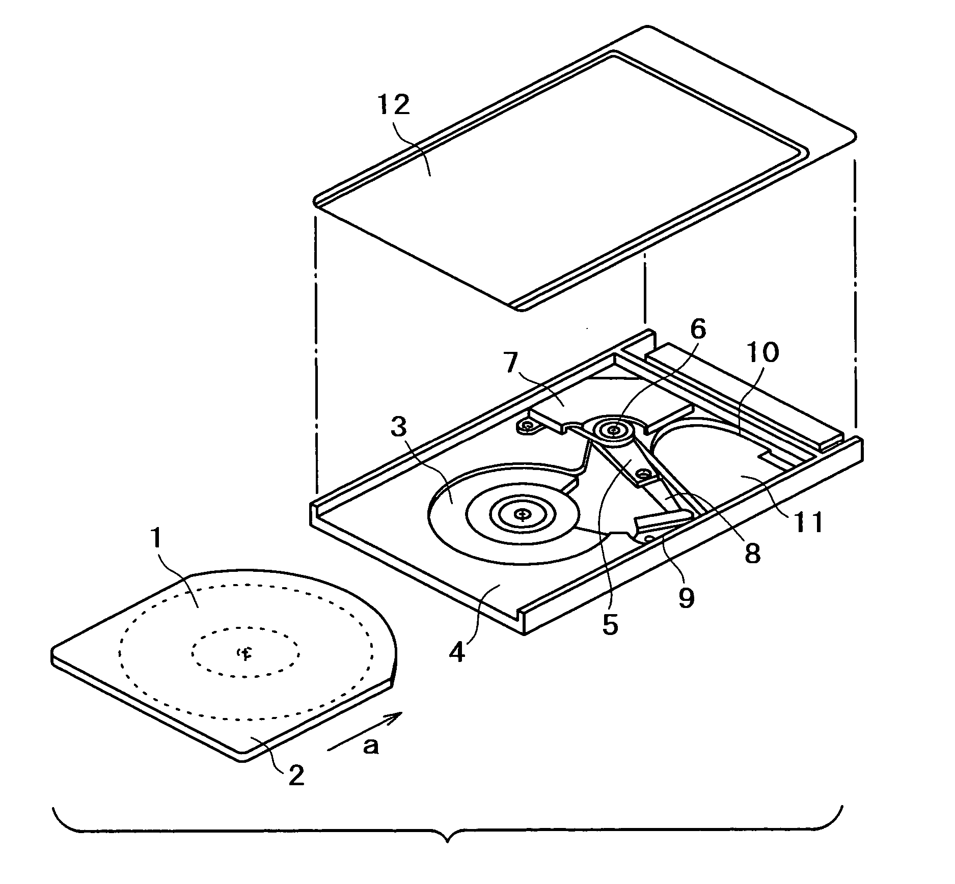
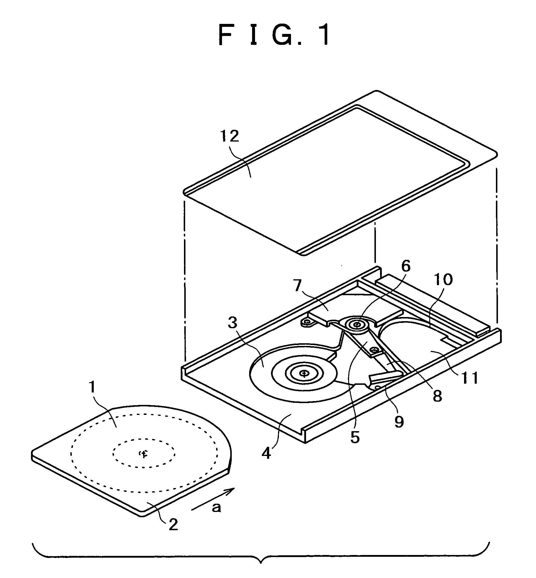
[0043]FIG. 1 is a perspective view showing a general configuration of an optical disk drive (optical disk apparatus) according to an embodiment of the present invention; FIG. 2 is a perspective view showing a general configuration of a swing arm unit of the optical pickup shown in FIG. 1; FIG. 3 is an exploded perspective view showing component units of the swing arm unit shown in FIG. 2 as viewed from above; and FIG. 4 is a similar view but showing the component units of the swing arm unit shown in FIG. 2 as viewed from below.

[0044] Referring to FIGS. 1 to 4, an optical pickup shown is an example of an optical disk drive formed such that an optical disk of a size of 85.6 mm long×54 mm wide×5 mm thick (for example, the type 2 size of the PCMCIA) can be exchangeably loaded. In FIG. 1, the optical pickup is shown with a top cover 12 removed.

[0045] An iron piece in the form of a disk having a hole perforated therein is adhered to a central portion of an optical disk 1 so that the iro...


PUM

PropertyMeasurementUnit
azimuth angleaaaaaaaaaa
thicknessaaaaaaaaaa
thicknessaaaaaaaaaa

Abstract

An optical pickup apparatus is disclosed which can be formed in a minimized thickness while realizing improvement in focusing servo performance, improvement in heat radiation, reduction of the voltage, reduction in number of parts, and reduction of the cost. A swing arm having an optical pickup includes an optical pickup base plate formed from a thin plate member of an iron alloy or a copper alloy, and a hole perforated in the optical pickup base plate is closed up from the opposite sides with a silicon substrate and a glass cover to form an enclosed space. An integrated optical pickup unit including a semiconductor laser and an optical system integrated on the silicon substrate is disposed in the enclosed space.

Description

BACKGROUND OF THE INVENTION [0001] This invention relates to an optical pickup apparatus, an optical disk apparatus and an optical pickup adjustment method for recording or reproducing an information signal on or from various optical disks. [0002] In recent years, reduction in thickness of optical disk drives has proceeded and is proceeding, and at present, a disk drive of approximately 10 mm thick is available as a commodity. The most serious obstacle to reduction in thickness of an optical disk drive is the thickness of an optical pickup which is a key device to the optical disk drive. [0003] Accordingly, reduction in thickness of the optical pickup is a key to production of an optical disk drive of a further reduced thickness. Recently, an optical pickup of a novel structure has been proposed in order to implement an optical disk drive of a reduced thickness such as, for example, 5 mm thick. [0004]FIG. 17 schematically shows a cross section of a typical one of related-art optical...

Claims


Application Information

Patent Timeline
Patent Type & Authority Applications(United States)
IPC IPC(8): G11B7/00G11B7/08G11B7/085G11B7/09G11B7/095G11B7/12G11B7/135G11B7/22
CPCG11B7/08523G11B7/08576G11B7/0927G11B7/094G11B7/0943G11B7/22G11B7/1203G11B7/1205G11B7/1374G11B7/1376G11B7/13925G11B7/095G11B7/122G11B7/123G11B7/09
Inventor KANAZAWA, TAKAKIYO
Owner SONY CORP
Why Eureka
Try Eureka