
Transfer member and image forming apparatus

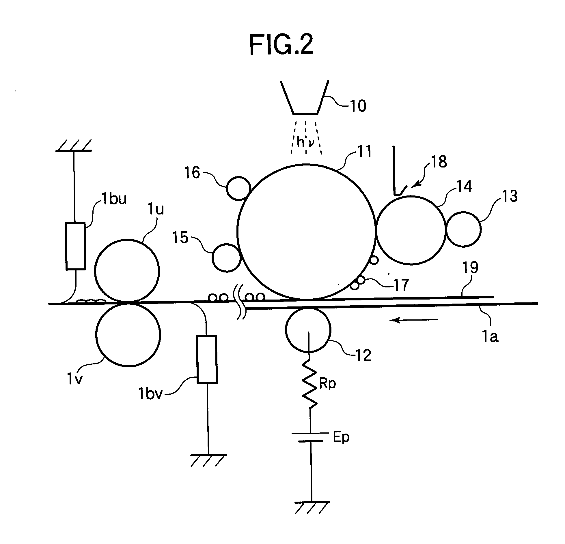
a technology of image forming apparatus and transfer member, which is applied in the direction of instruments, non-metal conductors, conductors, etc., can solve the problems of increasing the amount of current flowing into the non-print region of the transfer member, difficult adjustment of the transfer table, and low transfer efficiency, so as to reduce the load on the transfer power source, improve the printing quality, and reduce the effect of the load

Inactive Publication Date: 2005-05-05
OKI DATA CORP
View PDF1 Cites 11 Cited by
  • Summary
  • Abstract
  • Description
  • Claims
  • Application Information

AI Technical Summary

Benefits of technology

[0021] An object of the present invention is to provide a transfer member capable of obtaining excellent printing quality at low cost, reducing the load on a transfer power source, and increasing the lifetime of the transfer member.
[0023] Because the electrically conductive member (that contacts the image bearing member) of the transfer member is constructed as above, it becomes possible to lower the voltage dependence of the whole electrically conductive member even when another electrically conductive member (that forms a suitable nip against the toner image bearing member) has a high voltage dependence. Thus, it becomes possible to obtain excellent printing quality at low cost, to reduce the load on a transfer power source, and to increase the lifetime of the transfer member.

Problems solved by technology

The more rapid the current changes, the narrower the range of the transfer voltage becomes, and therefore it becomes difficult to adjust a transfer table.
Accordingly, the transfer efficiency is low, even when the total amount of the transfer current is large.
Moreover, when the transfer voltage increases, the amount of the current flowing into the non-print region of the transfer member also increases, and may cause an electric shock (i.e., a transfer shock) on the photosensitive drum.
As a result, the load on the transfer power source may increase, and the lifetime of the transfer member may be shortened.
Moreover, in the conventional transfer member whose voltage dependence ΔR is high (i.e., whose resistance is controlled by the semiconductive region), it is possible to lower the transfer voltage, but the leakage of the transfer current may occur in the vicinity of the end portion in the width direction of the recording medium, with the result that the transfer efficiency of the toner may decrease.
In particular, if the printing is performed on a thick paper having a narrow width, a back side of a postcard, or an end portion of a special media (for example, a film or an OHP sheet), a transferred image may become blurred, and therefore the printing quality may be degraded.
However, in order to add electrolyte or electrically conducive polymer to the conductive resilient portion of the transfer roller, the solubility to an insulation material is required.
Therefore, the choice of the insulation material, the electrolyte and the electrically conducive polymer are limited.
Thus, compared with the carbon black, the electrolyte and the electrically conducive polymer may become expensive, and therefore the cost of the transfer roller increases.

Method used


Image

  • Transfer member and image forming apparatus
  • Transfer member and image forming apparatus
  • Transfer member and image forming apparatus

Examples


embodiment 1

[0083] In Embodiment 1 of the present invention, the transfer / transport belt is manufactured as follows. Polypyrrole as electrically conducive polymer is solved in DMAC (Dimethylacetamide: (CH3)2NCOCH3) as solution. Isocyanate (R—N═C═O) is added to the solution, and then dopant from which OH-group and COOH group are removed is added to the solution. The resulting solution is formed into a cylindrical seamless body having a predetermined circumferential length by means of spin method. The seamless body is cut into pieces each of which has a predetermined length. As a result, the transfer / transport belt made of polyurethane resin to which polypyrrole (as an agent for providing electrical conductivity) is added is obtained.

[0084] It is preferable to use proton acid as the above described dopant. In particular, it is preferable to use the proton acid whose acid dissociation constant pKa is less than 4.8%. As such proton acid, it is possible to use, for example, inorganic acid (hydrochl...

embodiment 2

[0128] In Embodiment 2, the transfer roller is manufactured as follows. Acetylene black (as conductive particles) is added to silicone rubber (as insulation material). The adding amount of the acetylene black is 50 wt %. The silicone rubber to which acetylene black is added is extruded together with the shaft. The extruded body is vulcanized and foamed. Further, the extruded body is cut into pieces and is polished so that each piece has a predetermined length and a predetermined diameter, with the result that the transfer roller is obtained. Hereinafter, the transfer roller of Embodiment 2 having a conductive resilient portion made of high-conductive silicone to which acetylene black is added is referred to as a transfer roller SIcd.

[0129] In Embodiment 2, the transfer / transport belt is manufactured as was described in Embodiment 1. Polypyrrole is solved in DMAC as solution. Isocyanate is added to the solution, and then dopant from which OH-group and COOH group are removed is added...

embodiment 3

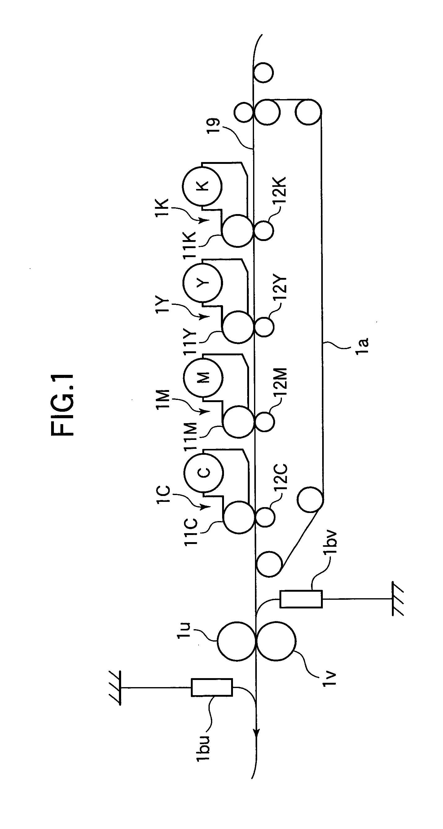
[0144] In a single-path printer shown in FIG. 1, while the toner is transferred to the recording medium in sequence at the transfer positions of the respective transfer units, the resistance increases as the thickness of the toner on the recording medium increases. Embodiments 1 and 2 have focused on the transferring of the toner at each transfer unit. However, in the single-path printer, four color toners are transferred to the recording medium in series, and therefore the resistance of the recording medium (including the toner) is higher at the transfer unit on the downstream side than at the transfer unit on the upstream side. In order to obtain the ideal transfer current (for example, 8.7 μA according to Experiment 2 of Embodiment 1), it is necessary to set the applied voltage of the transfer unit on the downstream side higher than the applied voltage of the transfer unit on the upstream side.

[0145]FIG. 27 shows the applied voltages of the transfer power sources Ep at the K, Y,...


PUM

PropertyMeasurementUnit
Currentaaaaaaaaaa
Electric potential / voltageaaaaaaaaaa
Electrical conductivityaaaaaaaaaa

Abstract

A transfer member is used in a transfer portion of an image forming apparatus. The transfer member includes an electrically conductive member that contacts a toner image bearing member of the image forming apparatus. The electrically conductive member is made of polyurethane resin to which electrically conducive polymer is added. An adding amount of the electrically conductive polymer with respect to the polyurethane resin is from 8 wt % to 40 wt %.

Description

BACKGROUND OF THE INVENTION [0001] This invention relates to a transfer member composed of electrically conductive members such as a transfer and transport belt and a transfer roller, and relates to an image forming apparatus using the transfer member. [0002] In an image forming apparatus such as a color electrophotographic printer (a tandem type printer) in which a recording medium is transported along a single path, a transfer voltage is applied by a transfer power source to a photosensitive drum and a shaft of a transfer roller. A transfer and transport belt (hereinafter, referred to as a transfer / transport belt) and a recording medium are nipped by the transfer roller and the photosensitive drum. Due to the transfer voltage, a toner is transferred from the photosensitive drum to the recording medium. [0003] As the toner moves from the photosensitive drum to the recording medium, and an electric charge also moves from a part of the surface of the photosensitive drum (where the to...

Claims


Application Information

Patent Timeline
IPC IPC(8): B32B27/40G03G15/14G03G15/01G03G15/16
CPCG03G2215/0119G03G15/1685Y10T428/31551
Inventor FURUYA, SATORUKISHIMOTO, MITSURU
Owner OKI DATA CORP
Learn More