Method and apparatus for improved baffle plate

Inactive Publication Date: 2005-05-12
TOKYO ELECTRON LTD
View PDF15 Cites 42 Cited by
  • Summary
  • Abstract
  • Description
  • Claims
  • Application Information

AI Technical Summary

Benefits of technology

[0007] According to another aspect, a disposable baffle plate for surrounding a substrate holder in a plasma processing system comprises a ring comprising a first edge configured to be coupled to the substrate holder, a second edge configured to be proximate a wall of the plasma processing system, and one or more passageways to permit the passage of gas there through, wherein the coupling of the first edge to the substrate holder facilitates centering the ring in the plasma processing system such th

Problems solved by technology

The erosion of exposed components in the processing system can lead to a gradual degradat

Method used


Image

  • Method and apparatus for improved baffle plate
  • Method and apparatus for improved baffle plate
  • Method and apparatus for improved baffle plate

Examples


Embodiment Construction

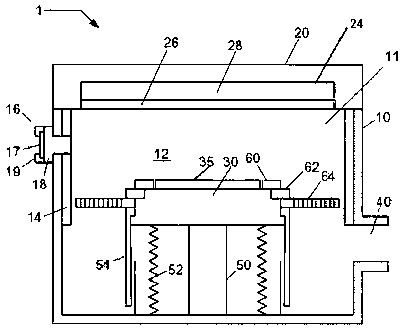
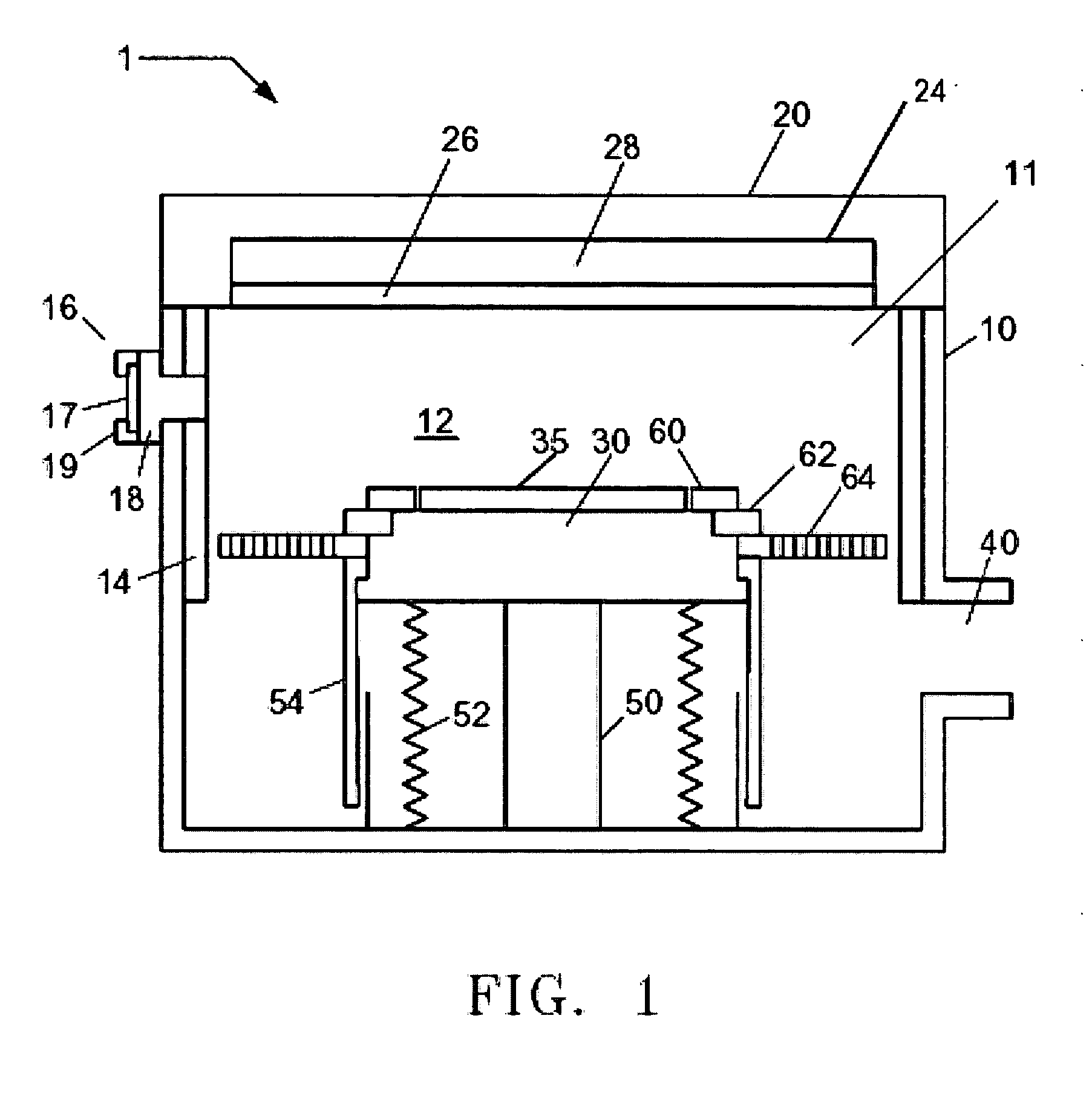
[0027] In plasma processing, a baffle plate can be employed to aid in confining the plasma to the processing region adjacent the substrate, as well as to affect the uniformity of fluid mechanic properties in the processing region adjacent the substrate. For conventional plasma processing systems, the baffle plate is configured to surround the substrate holder and, in many cases, the baffle plate is physically coupled to the substrate holder using fasteners. In general, the baffle plate comprises a plurality of openings to permit the passage of process gases, reactants and reaction products to the vacuum pumping system.

[0028] According to an embodiment of the present invention, a plasma processing system 1 is depicted in FIG. 1 comprising a plasma processing chamber 10, an upper assembly 20, an electrode plate assembly 24, a substrate holder 30 for supporting a substrate 35, and a pumping duct 40 coupled to a vacuum pump (not shown) for providing a reduced pressure atmosphere 11 in ...


PUM

PropertyMeasurementUnit
Sizeaaaaaaaaaa
Shapeaaaaaaaaaa

Abstract

A baffle plate assembly, configured to be coupled to a substrate holder in a plasma processing system, comprises a baffle plate having one or more openings to permit the passage of gas there through, wherein the coupling of the baffle plate to the substrate holder facilitates auto-centering of the baffle plate in the plasma processing system. For example, a centering ring mounted in the substrate holder can comprise a centering feature configured to couple with a mating feature on the baffle plate. After initial assembly of the plasma processing system, the baffle plate can be replaced and centered within the plasma processing system without disassembly and re-assembly of the substrate holder.

Description

FIELD OF THE INVENTION [0001] The present invention relates to a method and apparatus for utilizing a baffle plate in a plasma processing system and, more particularly, to a baffle plate assembly that facilitates improved assembly of the plasma processing system. BACKGROUND OF THE INVENTION [0002] The fabrication of integrated circuits (IC) in the semiconductor industry typically employs plasma to create and assist surface chemistry within a vacuum processing system necessary to remove material from and deposit material to a substrate. In general, plasma is formed within the processing system under vacuum conditions by heating electrons to energies sufficient to sustain ionizing collisions with a supplied process gas. Moreover, the heated electrons can have energy sufficient to sustain dissociative collisions and, therefore, a specific set of gases under predetermined conditions (e.g., chamber pressure, gas flow rate, etc.) are chosen to produce a population of charged species and c...

Claims


Application Information

Patent Timeline
IPC IPC(8): H01J37/32H01L21/00
CPCH01J37/32633H01L21/67069H01J37/32834H01L21/02
Inventor FINK, STEVEN T.STRANG, ERIC J.LAFLAMME, ARTHUR H. JR.WALLACE, JAYHYLAND, SANDRA
Owner TOKYO ELECTRON LTD
Why Eureka
Try Eureka