Systems and methods for non-destructively detecting material abnormalities beneath a coated surface

a technology of non-destructive detection and material abnormalities, applied in the direction of optical radiation measurement, instruments, machines/engines, etc., can solve the problems of damage to the material under the paint or coating, and inability to detect the abnormality by visual inspection,

Active Publication Date: 2005-05-12
ALFANO ROBERT R +1
View PDF8 Cites 98 Cited by
  • Summary
  • Abstract
  • Description
  • Claims
  • Application Information

AI Technical Summary

Problems solved by technology

In some instances, corrosion, cracking, or other damage (material abnormality) begins under the paint or coating and is undetectable by visual inspection.
In addition, the paint itself may crack, while the underlying surface is perfectly fine.
This may cause unnecessary repairs.
However, MOI's sensitivity to top-surface corrosion depends on the degree to which the eddy currents are altered and gives rise to anomalies in the induced magnetic field at the surface.
It has not been shown conclusively that the MOI technique can detect incipient corrosion that has not yet produced a significant increase in macroscopic surface roughness.
In addition, such equipment is prohibitively expensive for use on a wide scale.
However, for significant surface corrosion, AT and MOI have the potential to image significant surface corrosion damage and distinguish it from subsurface effects by employing commercially available instrumentation.
As a nondestructive technique for painted aircraft, visual techniques

Method used


Image

  • Systems and methods for non-destructively detecting material abnormalities beneath a coated surface
  • Systems and methods for non-destructively detecting material abnormalities beneath a coated surface
  • Systems and methods for non-destructively detecting material abnormalities beneath a coated surface

Examples


first embodiment

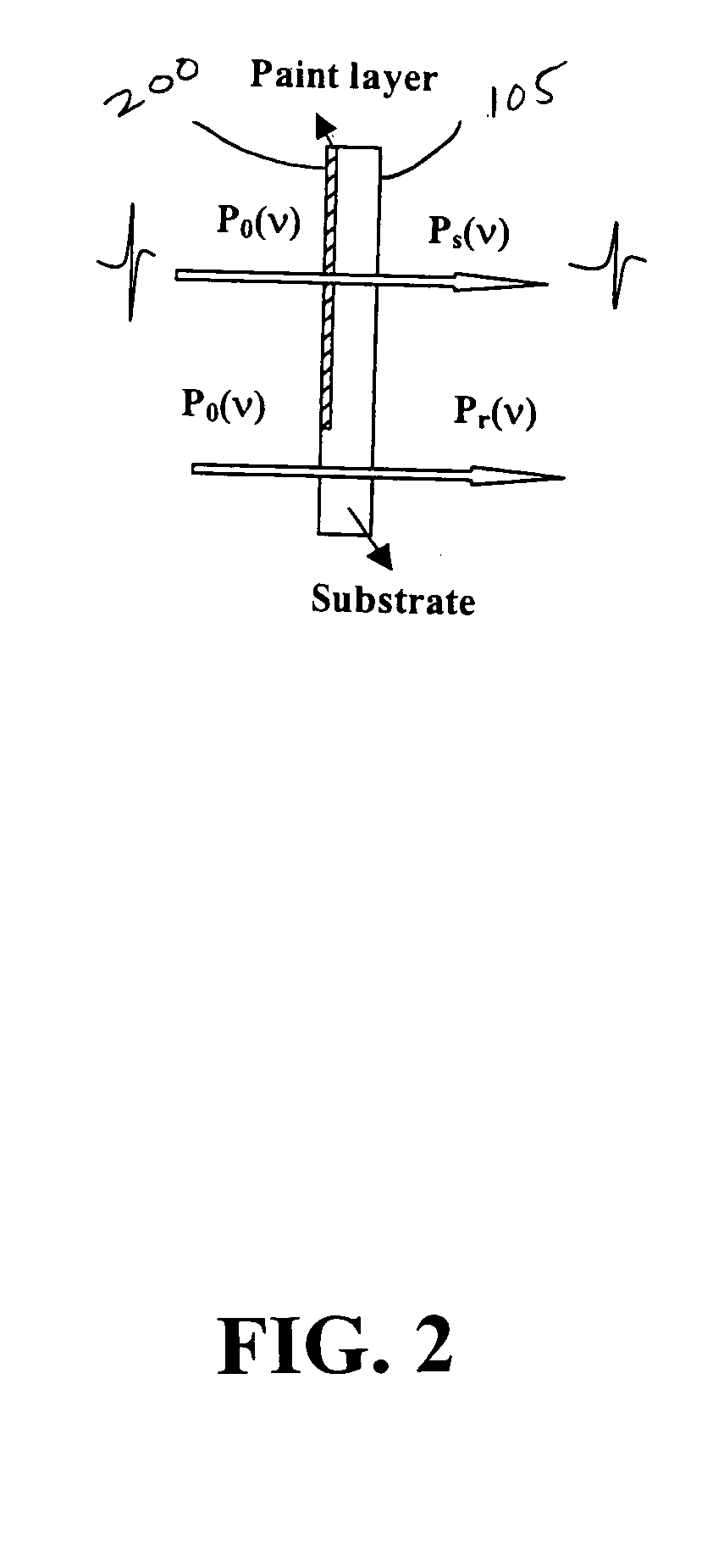
[0049]FIG. 2 is a cross-sectional view of a sample deposited on a polyethylene substrate to measure an optical transmission of a paint according to the present invention. The sample 105 includes a paint layer 200 deposited on the polyethylene substrate to measure the optical transmission of the paint against frequency (wavelength). Assuming the non-absorbing substrate has a refractive index of ns=1.52±0.01 at 300 K, the transmittance of the paint at different frequencies T(v) can be calculated from Equation (1). T⁡(v)=4⁢np2⁡(1+ns)2(1+np)2⁢(np+ns)2·Ps⁡(v)Pr⁡(v)(1)

[0050] In Equation (1), Ps(v) and Pr(v) are the transmitted powers of the THz light through the paint layer 200 and a reference, i.e., the non-covered portion of the substrate, respectively. np is the group refractive index of paint. Preferably, the thickness of the polyethylene substrate is approximately 4.0 mm to avoid interference peaks in the THz profile in the studied time zone arising from multiple reflections from th...

second embodiment

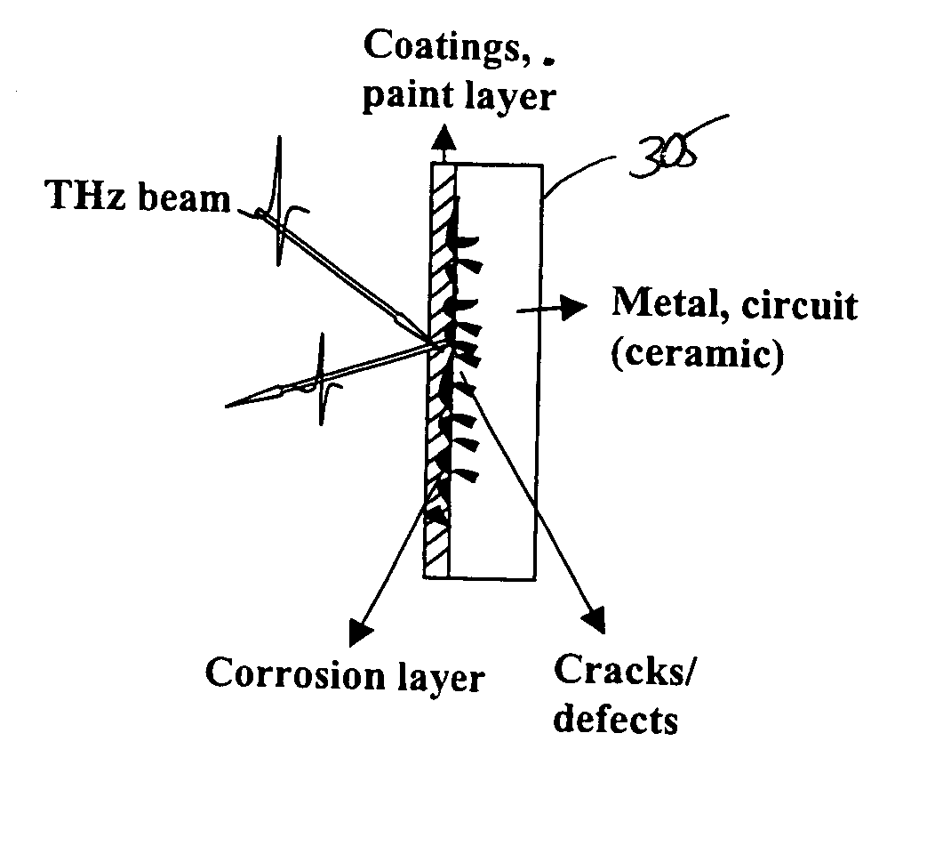
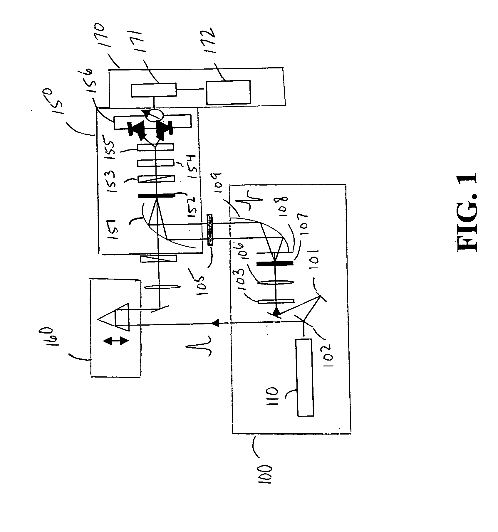
[0057]FIG. 4 is a cross-sectional view of a sample deposited on a polyethylene substrate to measure an optical transmission of a paint system according to the present invention. Referring to FIG. 4, the THz light focused to a diffraction-limited spot on the sample 305, and the reflected THz waveforms are acquired and processed in real time at each point of the sample. Preferably, the sample is scanned in x and y directions at a rate of approximately 10-20 pixels / s to form an image in the computer 172. By analyzing the temporal waveform reflected from the sample 305 at every pixel of the object in real time, information on the surface of the sample 305 can be inferred in many cases. Information under coatings of circuit boards, computer chips, bridges, boats, etc., about defects can be obtained using THz-TDS.

[0058] In lab experimentation, the THz transmittance spectra of paints and primers were obtained by measuring the transmitted power of Ps(v) and Pr(v) by THz-TDS and calculating ...


PUM


Abstract

The present invention provides systems and methods for non-destructively detecting material abnormalities beneath a coated surface. A terahertz (THz) illumination unit illuminates an area of the coated surface. A detection unit detects light reflected from the illuminated area of the coated surface, and a processing unit images the illuminated area of the coated surface from optical characteristics received from the detection unit.

Description

PRIORITY [0001] This application claims priority under 35 U.S.C. § 119 to a provisional application entitled “Terahertz Transmission Window to Detect and Image Corrosion, Defects and / or Cracks Beneath Paint or Primer, Coatings Layers of a Surface” filed in the United States Patent and Trademark Office on Sep. 24, 2003 and assigned Ser. No. 60 / 505,441, the contents of which are hereby incorporated by reference.GOVERNMENTAL INFORMATION [0002] This invention is supported in part by: New York State Office of Science, Technology and Academic Research.BACKGROUND OF THE INVENTION [0003] 1. Field of the Invention [0004] The present invention relates generally to systems and methods for non-destructively detecting material abnormalities beneath a surface, and in particular, to systems and methods for detecting corrosion and cracks in metal surfaces beneath a layer of paint using a terahertz (THz) imaging technique. [0005] 2. Description of the Related Art [0006] Paint or other coatings are t...

Claims


Application Information

Patent Timeline
IPC IPC(8): G01N21/17G01N21/35
CPCG01N21/3581G01N21/3563G01N21/8422
Inventor ALFANO, ROBERT R.YU, BAOLONG
Owner ALFANO ROBERT R
Why Eureka
Try Eureka