Conventionally used “dimmers” frequently are not actually saving any energy as many simply use a
resistor which is placed in the circuit with the light being dimmed to absorb current that would otherwise be available to the light.
The longer the void created in the
current cycle, the less current is available to the attached device, however the greater the interruption in the timing and the greater the difference between the output frequency and input frequency.
However, such devices in chopping a
single segment from one side of the
current cycle play havoc with electrically powered devices which depend upon the continuing and constant oscillation of the
current cycle providing a
timer to the attached device.
Computers and induction motors and similar devices seeking the constant 60 Hz or 50 Hz cycles of
line current are seriously impaired for function when a large portion of one cycle is void of
electrical current.
Some devices may even falsely sense that the current is reversing if the segment of current void for a
sufficient time increment, thus disabling the device or even causing damage to the circuits when the current restarts.
Another serious problem arises in the use of induction style AC electric motors which are major energy consumers and thus a major target for electrical
energy conservation.
This current interruption throws the current frequency out of balance and plays havoc with the fields formed inside the motor by the windings since they are spaced to take
advantage of the 60 Hz or 50 Hz frequency in generating the fields around the armature.
Interrupting the current flow in a
single segment section during one oscillation collapses the
magnetic field during the time that the current is interrupted and either throws the motor out of balance causing erratic rotation, overheating, and eventual failure of the device.
Lengthening the interruption as is conventionally done with light
bulb dimmers to lower the output, further increases the damage done to the running of the
induction motor by further collapsing the magnetic fields and throwing the device out of balance.
Consequently conventional
dimmer style current interruption devices will not function upstream in the power suppled in such a circuit since the subsequent device downstream in the circuit tries to
undo the interruption of current which the
dimmer chops from one side of the AC oscillation.
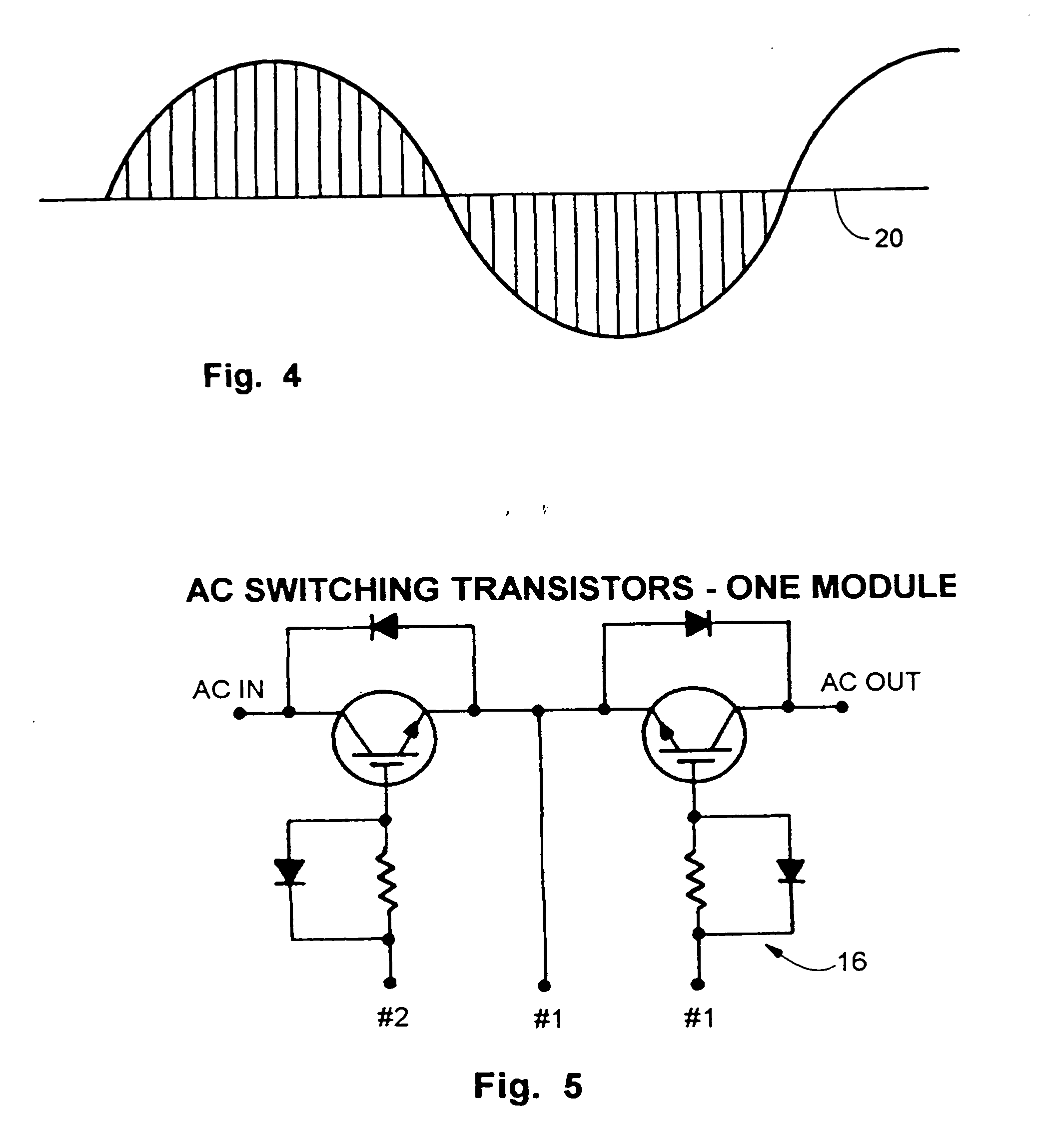
Since each complete cycle of a conventional 60 Hz
AC circuit used in the United States takes only one second, the duration of each of the twenty-five interruptions on both oscillations is extremely short.
Further, since there are so many short interruptions, lengthening or shortening each interruption varies the effective maximum current available to the circuit widely without causing the devices attached to sense an end to the negative or positive oscillation of the cycle.
However, Smith teaches a constant pulse or current
interruption duration and varying the frequency of the line output and requires a power
transformer and chokes to accomplish the task.
This makes the device bulky and yields the potential of damage to frequency specific devices such as induction motors and computers.

