
System and method to reduce laser noise for improved interferometric laser ultrasound detection

a laser ultrasound and laser noise reduction technology, applied in the field of ultrasound generation and detection, can solve the problems of adversely increasing the manufacturing cost of composite structures, requiring strict quality control procedures in the manufacturing process, and labor-intensive nde methods, and achieve high snr laser ultrasound measurements

Active Publication Date: 2005-05-12
LOCKHEED MARTIN CORP
View PDF15 Cites 35 Cited by
  • Summary
  • Abstract
  • Description
  • Claims
  • Application Information

AI Technical Summary

Benefits of technology

The present invention provides an improved method and system for detecting ultrasonic surface displacements on a remote target using laser ultrasound. The system includes a laser to generate ultrasonic displacements and a detection laser to collect the displaced light. An optical filter removes noise from the detection laser beam, resulting in higher signal-to-noise ratios. The system can quickly detect defects within materials, such as composite material, without the need for averaging over time.

Problems solved by technology

While composite materials offer significant improvements in performance, they require strict quality control procedures in the manufacturing processes.
Conventional NDE methods are slow, labor-intensive, and costly.
As a result, testing procedures adversely increase the manufacturing costs associated with composite structures.
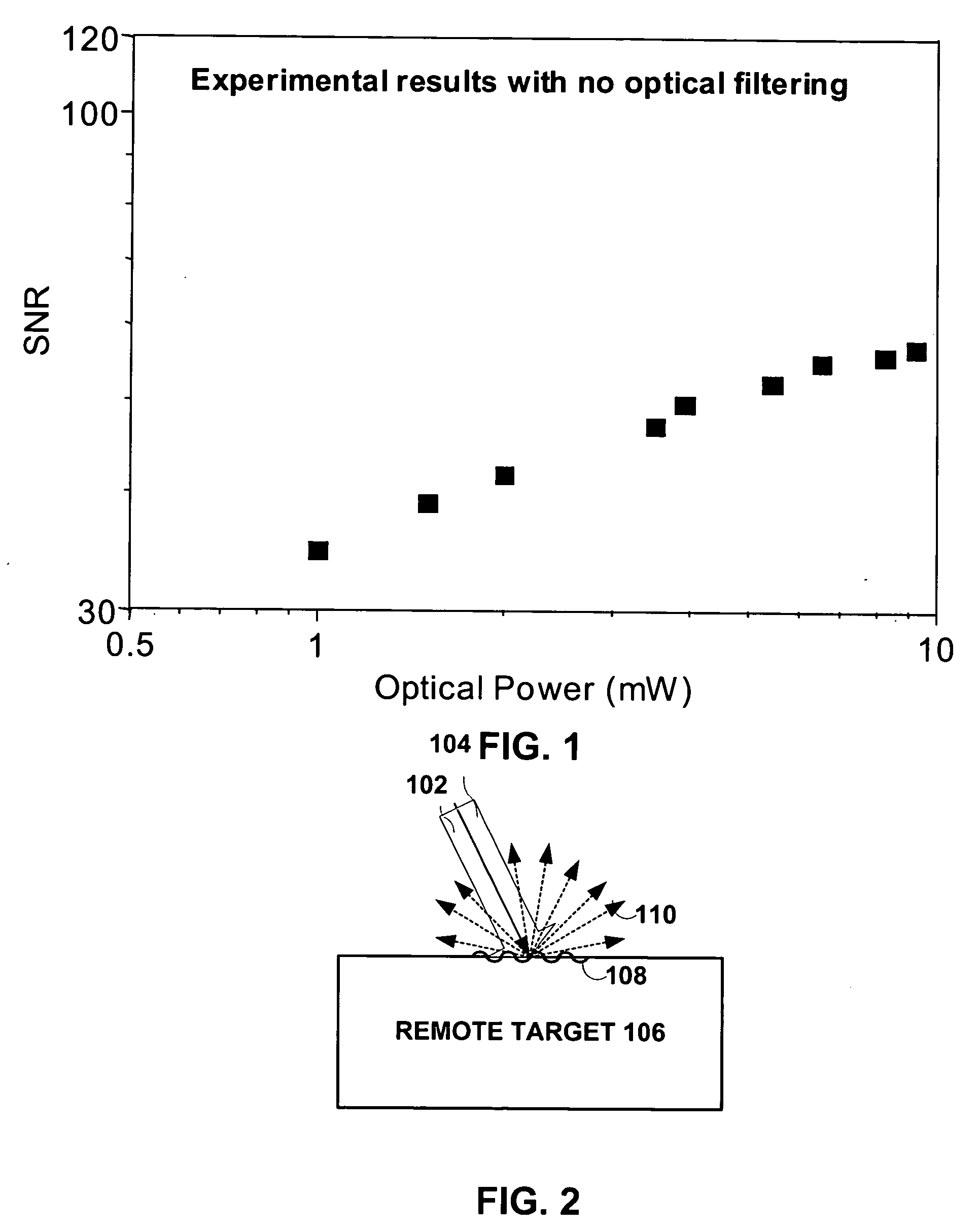
However, in practice, as the SNR increases, measurements become more and more sensitive to laser noise.
Even when using the quietest single-mode lasers, laser-ultrasound SNR is limited to a maximum value even when detected light power keeps increasing.
Although SNR improves with this configuration, SNR can become limited by phase noise for large quantities of detected light.
However, averaging is slow and SNR increases as the square root of the number of averages.
Averaging is therefore an expensive and time-consuming option.

Method used


Image

  • System and method to reduce laser noise for improved interferometric laser ultrasound detection
  • System and method to reduce laser noise for improved interferometric laser ultrasound detection
  • System and method to reduce laser noise for improved interferometric laser ultrasound detection

Examples


Embodiment Construction

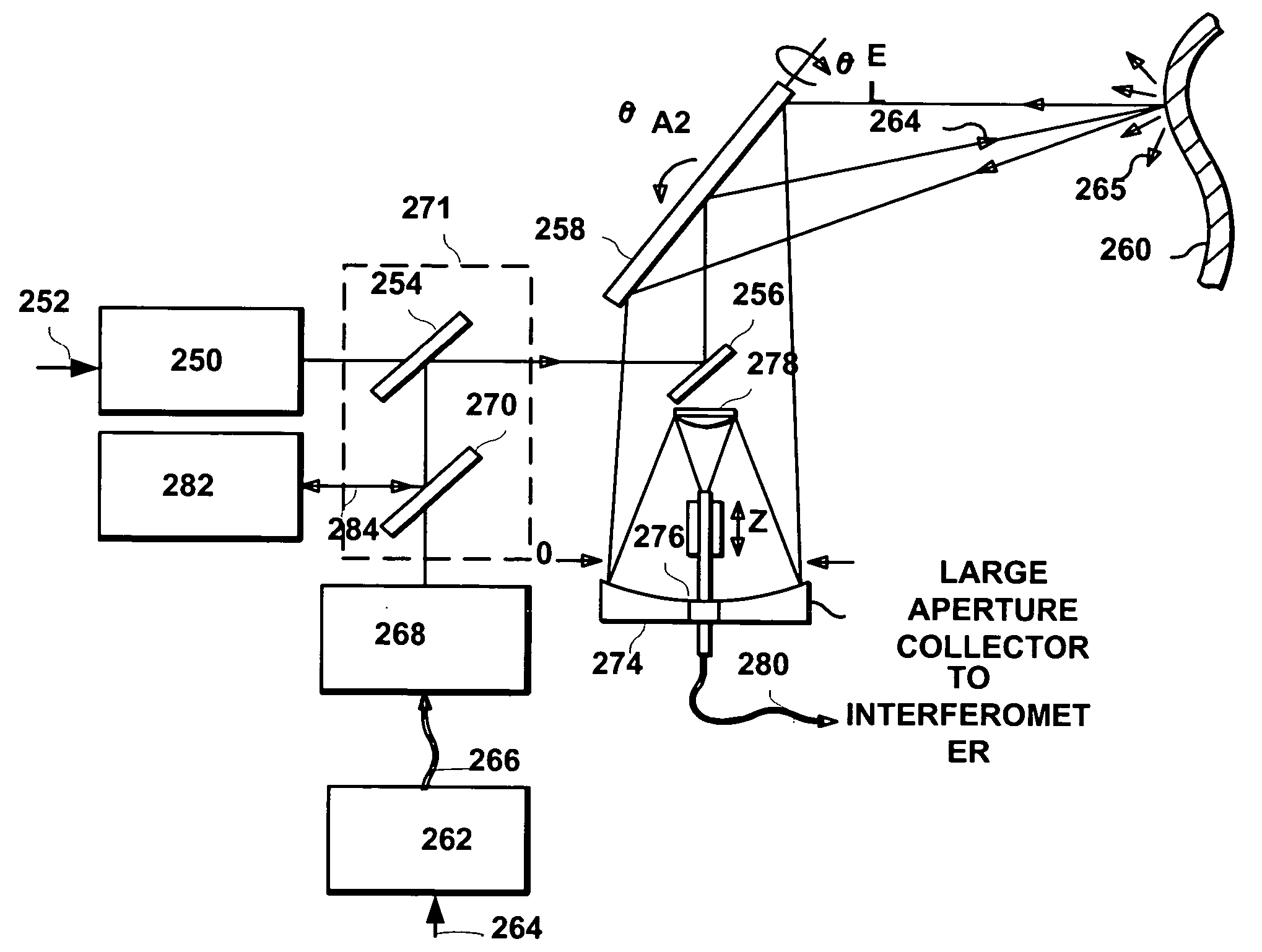
[0023] Embodiments of the present invention are illustrated in FIG. 5, like numerals being used for like and corresponding parts of the various drawings.

[0024]FIG. 2 illustrates two incoming laser beams, which include a laser beam 102 to generate ultrasound and a detection laser beam 104 to detect the ultrasound at a remote target 106, such as a composite material under test. These lasers may be coaxially applied to remote target 106. Generation laser beam 102 causes thermoelastic expansion in target 106 in the form of ultrasonic deformations 108. Deformations 108 modulate, scatter and reflect detection laser beam 104 to produce phase-modulated light 110 directed away from target 106.

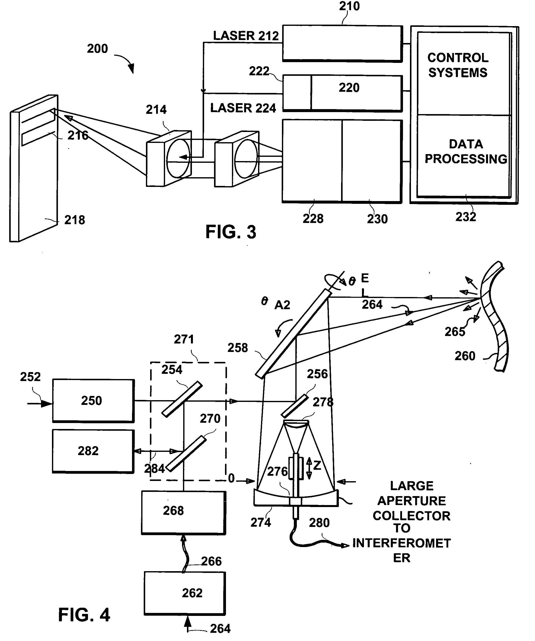
[0025]FIG. 3 provides a block diagram with the basic components for performing ultrasonic laser testing. Generation laser 210 produces a laser beam 212 which optical assembly 214 directs to composite material 216 under test. As shown, optical assembly 214 includes a scanner or other like mechanism tha...


PUM


Abstract

The present invention provides an optical filter assembly that reduces the phase and amplitude noise of a detection laser used to detect ultrasonic displacements. The filtered detection laser is directed to the surface of a remote target. Ultrasonic displacements at the surface scatter the filtered detection laser. Collection optics then gather phase modulated light scattered by the surface and direct the phase modulated light to an optical processor to produce a signal representative of the ultrasonic displacements with an improved SNR. Additional processors may determine the structure of the remote target.

Description

TECHNICAL FIELD OF THE INVENTION [0001] The present invention relates generally to the generation and detection of ultrasound in materials using lasers, and more particularly, to a system and method that significantly reduces laser noise for laser ultrasound detection. BACKGROUND OF THE INVENTION [0002] In recent years, the use of advanced composite structures has experienced tremendous growth in the aerospace, automotive, and many other commercial industries. While composite materials offer significant improvements in performance, they require strict quality control procedures in the manufacturing processes. Specifically, non-destructive evaluation (NDE) methods must assess the structural integrity of composite materials. This assessment detects inclusions, delaminations and porosities. Conventional NDE methods are slow, labor-intensive, and costly. As a result, testing procedures adversely increase the manufacturing costs associated with composite structures. [0003] Various method...

Claims


Application Information

Patent Timeline
Patent Type & Authority Applications(United States)
IPC IPC(8): G01B9/02G01H9/00
CPCG01H9/00
Inventor DUBOIS, MARCBURR, KENT C.DRAKE, THOMAS E. JR.LORRAINE, PETER W.
Owner LOCKHEED MARTIN CORP
Learn More