Card type device capable of reading fingerprint and fingerprint identification system

a card type and fingerprint detection technology, applied in the direction of portable computer details, program control, instruments, etc., can solve the problems of high cost, pc cards equipped with such fingerprint reading sensors can be hardly carried, and problems such as problems such as the inability to carry,

Inactive Publication Date: 2005-05-12
CASIO COMPUTER CO LTD
View PDF9 Cites 12 Cited by
  • Summary
  • Abstract
  • Description
  • Claims
  • Application Information

AI Technical Summary

Benefits of technology

[0024] a control unit for identifying as to whether or not the fingerprint data transmitted from the card type device is made coincident with previously-registered fingerprint data, and for restr

Problems solved by technology

However, if the fingerprint reading sensor is provided on the surface of the PC card, then the following problem may occur.
Also, if the fingerprint sensor is provided on any position other than the PC card insertion portion, then another problem may occur.
That is, when this PC card is loaded in the PC card slot, since this PC card is largely projected out from the PC card slot, the PC card equipped with such a fingerprint reading sensor can be hardly carried while this PC card is continuously loaded on the electronic appliance.
Since these fingerprint reading sensors employ such expensive semiconductor devices as a CCD, high

Method used


Image

  • Card type device capable of reading fingerprint and fingerprint identification system
  • Card type device capable of reading fingerprint and fingerprint identification system
  • Card type device capable of reading fingerprint and fingerprint identification system

Examples


first embodiment

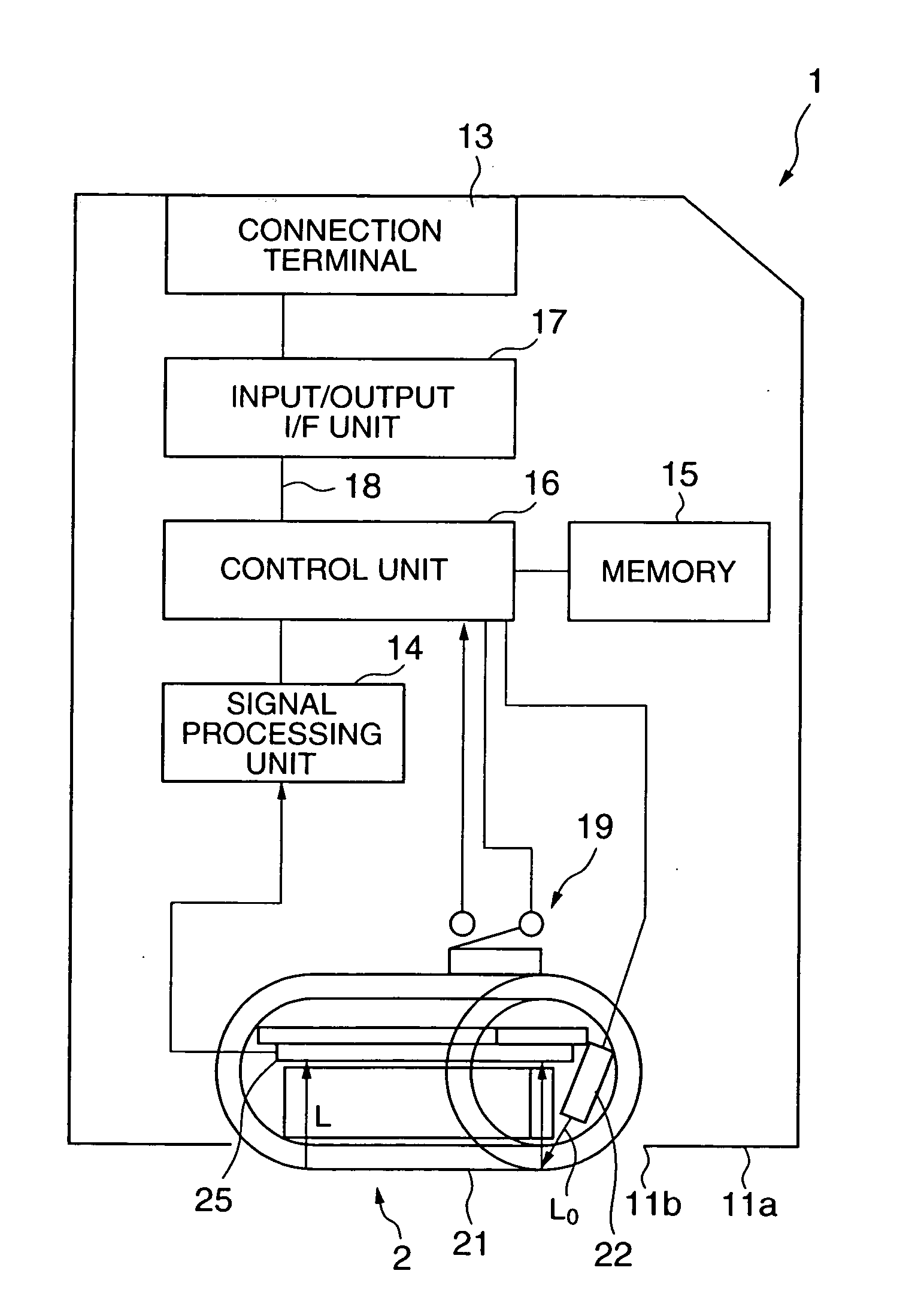
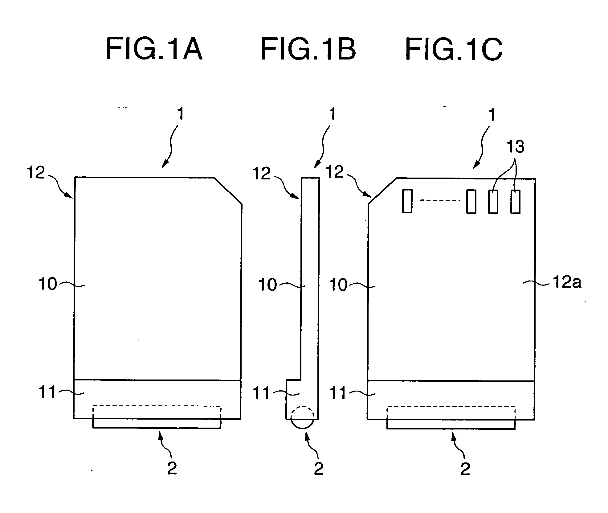
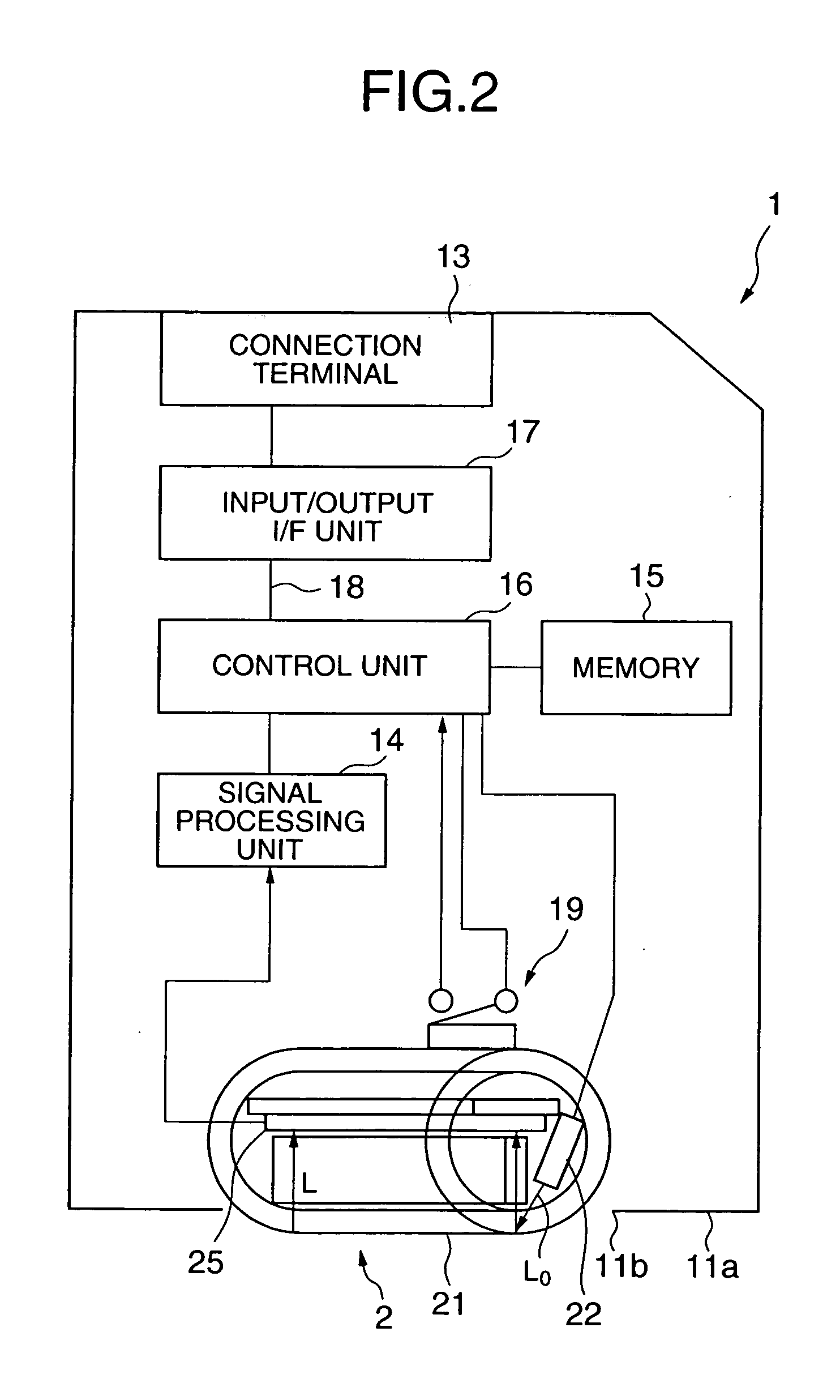
[0040]FIG. 1 shows an outer appearance view of a card type device 1 according to the present invention. The card type device 1 contains a memory member having a predetermined storage capacity, and is used in such a manner that this card type device 1 is inserted into a card slot provided with an electronic appliance. This card type device 1 corresponds to, for example, a standardized memory card known as a PC (Personal Computer) card, a CF (Compact Flash) card, an SD (Secure Digital) memory card, and MMC (Multi-Media Card). In a housing 10 of this card type device 1, a fingerprint reading unit 2 is provided on one edge portion 11, and a connection terminal 13 is provided on a rear surface 12a of the other edge portion 12. This connection terminal 13 is employed so as to be electrically connected to an electronic appliance. Also, in the card type device 1, the other edge portion 12 of the housing 10 thereof constitutes an insertion portion which is inserted into a card slot of the el...

second embodiment

[0093]FIG. 9 schematically shows an internal arrangement of the card type device 7 according to the present invention. The card type device 7 contains a program memory 71 which has stored thereinto a fingerprint identification program, and a data memory 72 which has stored thereinto fingerprint data of regular users.

[0094] In the second embodiment, a user identification process operation is carried out based upon a fingerprint identification process operation on the side of a control unit 16 of the card type device 7. In this case, the control unit 16 executes the fingerprint identification process operation in accordance with the fingerprint identification program stored in the program memory 71. In this fingerprint identification process operation, the control unit 16 identifies such a fingerprint data which has been synthesized based upon one-dimensional fingerprint data acquired from the fingerprint reading unit 2 with respect to such a fingerprint data which has been stored in ...

third embodiment

[0099] As shown in FIG. 10, a card type device 8, according to he present invention, contains an encrypting circuit 81, and a secret key memory 82 which has stored thereinto secret encryption keys. The signal processing unit 14, the memory 15, the control unit 16, the encrypting circuit 81, and the secret key memory 82 of this card type device 8 have been integrated in an identification chip having an tamper resistant characteristic.

[0100] The expression “tamper resistant” implies a function capable of resisting physical shocks (illegal accesses, alternations etc.) to some extent. In other words, this card type device 8 is equipped with such a physical structure and a preventing means as follows: The physical structure cannot allow illegal accesses to this card type device 8, which are issued from an external source. Also, in such a case that the card type device 8 is tried to be disassembled so as to electronically analyze the secret keys and the like, the preventing means can prev...


PUM


Abstract

A card type device is mounted on a card slot of an electronic appliance. In the card type device, a transparent cylindrical-shaped roller is provided at an edge portion of a housing in such a manner that an outer peripheral plane of this roller is projected from the edge portion. Also, a one-dimensional image sensor is provided inside the roller, while the one-dimensional image sensor acquires one-dimensional fingerprint data of a finger of a user, and this finger abuts against the outer peripheral plane of the roller. Since the finger a butting against the outer peripheral plane of the roller is moved, this roller is rotated, so that one-dimensional fingerprint data which are continuously acquired by the one-dimensional image sensor are synthesized with each other to produce fingerprint data as a two-dimensional image. The synthesized fingerprint data is transmitted to the electronic appliance, and then fingerprint identification is carried out by the electronic appliance.

Description

BACKGROUND OF THE INVENTION [0001] 1. Field of the Invention [0002] The present invention is related to a card type device having a fingerprint reading function and a fingerprint identification system using the card type device. [0003] 2. Description of the Related Art [0004] Very recently, since electronic appliances are gradually utilized in the network form, communications are freely established among these electronic appliances connected to each other via networks, so that various sorts of information thereof may be accessed everywhere. In connection with such a network operation, needs of security aspects capable of preventing illegal accesses made by third party are increased. [0005] As one of such security techniques, a method capable of identifying a regular user by checking a fingerprint has been proposed, and a fingerprint reading sensor is provided on a PC card. When a user depresses his finger on a fingerprint sensor of such a PC card, a fingerprint of this finger is acq...

Claims


Application Information

Patent Timeline
IPC IPC(8): G06F15/02G06F1/00G06F1/16G06F21/00G06K9/00G06K19/077G06K19/10G11C16/22H04M1/667H04M1/675H04M1/724
CPCG06F1/1613H04M2250/14G06F1/1656G06F21/32G06F21/34G06F21/78G06K9/00026G06K19/0718G06K19/077G06K19/07732G11C16/22H04M1/667H04M1/675H04M1/72519G06F1/1632H04M1/724G06V40/1335G06F18/00
Inventor KITA, KAZUNORI
Owner CASIO COMPUTER CO LTD
Why Eureka
Try Eureka