System and method for control of fluid dispense pump

a fluid dispense pump and fluid technology, applied in the direction of piston pumps, combustion types, vessel construction, etc., can solve the problems of limiting system speed and accuracy, and affecting the operation of fluid dispense pumps. , to achieve the effect of reducing the likelihood of fluid “balling up” and/or clogging, promoting uniform distribution and reducing system pressur

Inactive Publication Date: 2005-05-12
DL TECH
View PDF99 Cites 13 Cited by
  • Summary
  • Abstract
  • Description
  • Claims
  • Application Information

AI Technical Summary

Benefits of technology

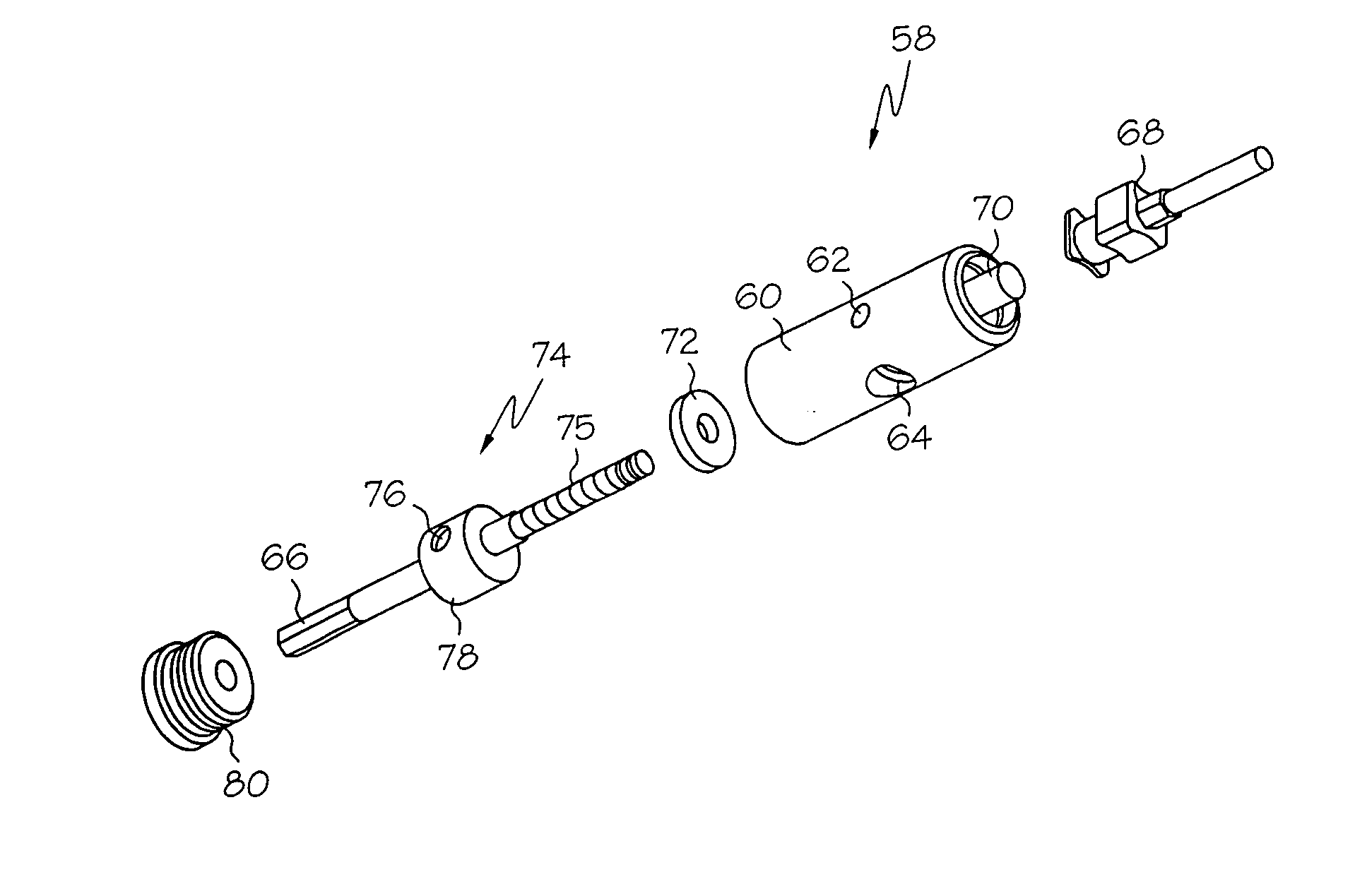
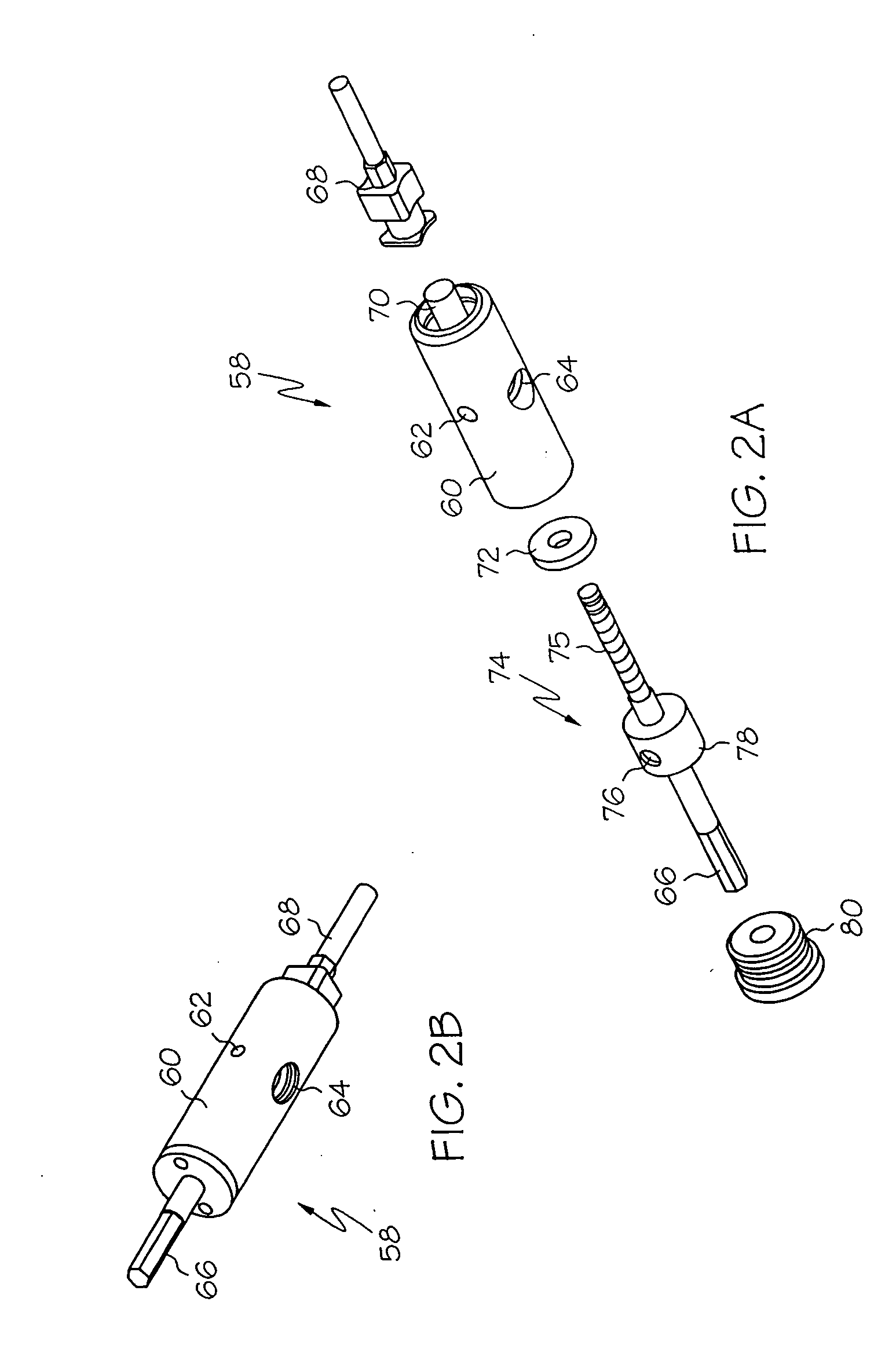
[0011] In a first aspect, the present invention is directed to a cartridge adapted for use with a fluid pump. The cartridge includes a material inlet port, a material outlet port, a feed screw, and a reservoir. The feed screw is disposed longitudinally through the body of the cartridge for delivering fluid provided at the inlet port to the outlet port. The inlet port takes the form of an elongated port provided at a side portion of the feed screw proximal to allow for fluid provided at the inlet port. This elongated configuration promotes even distribution of fluid during transport by the feed screw, and lowers system pressure, thereby reducing the likelihood of “balling-up” and / or clogging of fluid.
[0012] The inlet port is preferably provided through the cartridge body at an acute angle relative to the reservoir to allow for gravity-assisted fluid delivery. The inner portion of the cartridge may be lined with a carbide or plastic (for example Teflon, torlon, or tercite) liner having an aperture aligned with the inlet port to enhance ease of cleaning. The elongated port of the cartridge may be provided in a wall of the carbide liner.
[0013] In another aspect, the present invention is directed to a release bracket for mounting the syringe and cartridge to the body of the pump. In this manner, the syringe, feed tube, and cartridge can be dismantled from the pump body as a unit, allowing for joint storage of the syringe, feed tube and cartridge, while minimizing risk of contamination of the material. Additionally, once the system is initially purged of extraneous gas during initialization, the purged system can be stored as a unit without the need for re-initialization prior to its next use.
[0014] In another aspect, the present invention is directed to a fluid pump assembly that employs an electronically-operated servo-motor assembly. A closed-loop servo motor having a rotary encoder is adapted for controlling rotation and position of the feed screw with heightened accuracy, as compared to those of conventional clutch-driven assemblies. For example, in a preferred embodiment, a rotary encoder capable of 8192 counts in a 360 degree range may be employed to achieve dispensing resolution to a degree that is orders of magnitude greater than conventional systems. Servo-motor-based systems further confer the advantages of small, lightweight systems well-suited for high-performance operation. Electronic control allows for complete determination of the acceleration / deceleration of feed screw rotation, allowing for application-specific flow profiles. An orbital gear transmission unit may be provided between the motor and the pump feed screw for providing further accuracy in controlling the feed screw; for example a 7:1 reduction may be applied to provide 57,344 counts over a 360 degree range.
[0015] In another aspect, the present invention is directed to a pump assembly that is compatible with both floating-z and fixed-z cartridges and dispensing tips. A quick-release pin, which may be spring-biased, is provided on the side of the cartridge body to allow for removal / insertion of cartridges. A fixed-z cartridge includes a hole for receiving the quick-release pin in a fixed relationship. A floating-z cartridge includes a longitudinal groove to permit longitudinal travel of the pin in the groove, and thus allow for floating-z operation.

Problems solved by technology

Such conventional pump systems suffer from several limitations.
The motor and rotary clutch mechanisms are bulky and heavy, and are therefore limited in application for modem dispensing applications requiring increasingly precise, efficient, and fast operation.
The excessive weight limits use for those applications that require contact of the pump with the substrate, and limits system speed and accuracy, attributed to the high g-forces required for quick movement of the system.
The mechanical clutch is difficult to control, and coasts to a stop when disengaged, resulting in deposit of excess fluid.
However, the spring adds to the length of the cartridge, and contributes to system complexity.
This leads to inconsistent material flow.
This further limits material flow and can contribute to material “balling” and clogging.
Since the tube and bracket are on opposite sides of the bracket, removal of the syringe from the pump body requires dismantling of the tube and syringe, which can contaminate fluid material positioned at the interface during disassembly.
Further, since the syringe and cartridge can not be removed and stored together as a unit, disassembly and cleaning of the cartridge is required.
Additionally, the inlet neck is narrow and therefore difficult to clean.
While such pumps are adequate for operations requiring relatively large dispensing volumes, at smaller volumes the system resolution is relatively limited, since the timing signal is relatively inaccurate at shorter time periods, and since residual motion in the clutch or brush motor is difficult to predict.
Assuming the platform / pump controller to be a computer-based system, the time-period-based signal may be subject to even further variability, since initiation of the signal may be delayed while other tasks are processed by the computer.

Method used


Image

  • System and method for control of fluid dispense pump
  • System and method for control of fluid dispense pump
  • System and method for control of fluid dispense pump

Examples


Embodiment Construction

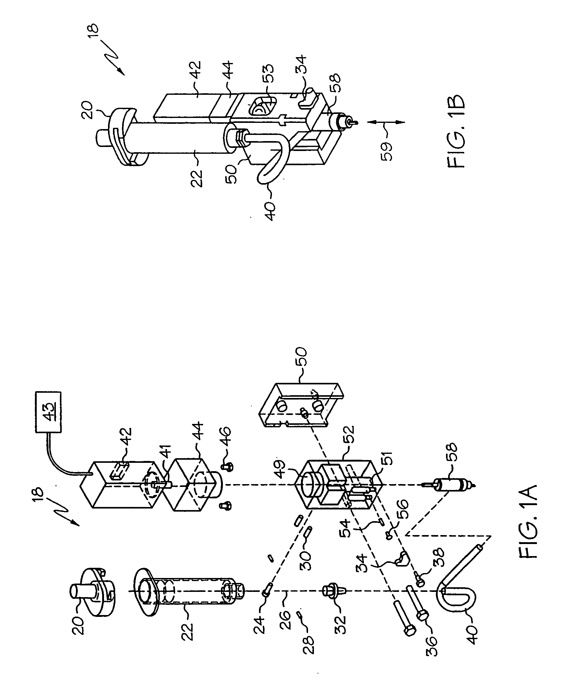
[0047]FIGS. 1A and 1B are an exploded perspective view and an assembled perspective view respectively of a pump assembly configured in accordance with the present invention. With reference to FIGS. 1A and 1B, an embodiment of the dispensing pump 18 comprises a motor 42, an optional transmission box 44, a pump housing 52, and a cartridge 58.

[0048] The motor 42 preferably comprises a closed-loop servo motor with an independent motion controller 43. The motion controller 43 may be provided by the host dispensing platform, and may comprise, for example, a Delta Tau controller, Northbridge, Calif., USA. The closed-loop servo motor may comprise, for example, a Sigma Mini Series motor, produced by Yaskawa Electric Corp., Japan. Feedback is preferably provided by a rotary encoder, for example providing 8192 discrete counts over 360 degree rotation. The motor 42 includes an axle 41 which operates to drive the feed screw in the cartridge assembly 58 (described below). In this manner, high-pe...


PUM


Abstract

In a fluid pump and cartridge assembly, a cartridge includes a material inlet port, a material outlet port, and a feed screw. The feed screw delivers fluid to be dispensed from the fluid inlet to the outlet port. The fluid inlet is preferably elongated in a direction along a longitudinal axis of the feed screw to enhance consistency in material flow through the cartridge. The feed screw is preferably driven by a closed-loop servo motor to achieve high-performance dispensing resolution. The assembly is preferably compatible with fixed-z and floating-z cartridges. A optional vented dispense tip, in combination with the fluid pump, allows for repeatable deposit of fillet patterns while maintaining optimal consistency. A dispense controller allows for reverse-compatibility such that the fluid pump of the present invention can be mounted to, and controlled by, conventional pump position controllers.

Description

RELATED APPLICATIONS [0001] This application is a Continuation of Ser. No. 10 / 054,084, filed Jan. 22, 2002, which is a Continuation-in-Part of U.S. patent application Ser. No. 10 / 038,381, filed Jan. 4, 2002, which is a Continuation-in-Part of U.S. patent application Ser. No. 09 / 702,522, filed Oct. 31, 2000, now U.S. Pat. No. 6,511,301, and which is a Continuation-in-Part of U.S. patent application Ser. No. 09 / 491,615, filed Jan. 26, 2000, now U.S. Pat. No. 6,547,167, the contents of each being incorporated herein by reference, in their entirety.BACKGROUND OF THE INVENTION [0002] Contemporary fluid dispense systems are well suited for dispensing precise amounts of fluid at precise positions on a substrate. A pump transports the fluid to a dispense tip, also referred to as a “pin” or “needle”, which is positioned over the substrate by a micropositioner, thereby providing patterns of fluid on the substrate as needed. As an example application, fluid delivery systems can be utilized for...

Claims


Application Information

Patent Timeline
Patent Type & Authority Applications(United States)
IPC IPC(8): B05C11/10B05C17/005
CPCB05C11/10F04B13/00B05C17/00503B05C11/1034
Inventor FUGERE, JEFFREY P.
Owner DL TECH
Why Eureka
Try Eureka