CO generator

a generator and co-generation technology, applied in the direction of gasification process details, fuel cells, combustible gas production, etc., can solve the problems of not meeting the demands of an efficient continuous co-generation installation in many respects, complex elements built into the reactor, and high demands for energy saving and energy saving

Inactive Publication Date: 2005-05-12
BAYER MATERIALSCIENCE AG
View PDF12 Cites 13 Cited by
  • Summary
  • Abstract
  • Description
  • Claims
  • Application Information

AI Technical Summary

Benefits of technology

[0024] A further object of the invention was to provide a continuous process for the production of CO gas by the gasification of coal using the generator according to the inventi

Problems solved by technology

However, it does not meet the demands of an efficient continuous CO gas production installation in many respects.
This process has the disadvantage that the elements built into the reactor are very complex and make high demands of the flowability of the solid material in order to avoid blockages and hence impairment of the combustion process.
In addition, they represent a cost factor in the construction and maintenance of the installation and reduce the space-time yield of the reactor to a not inconsiderable degree.
A disadvantage of this process is the formation of a flame at the burner and its predominantly horizontal orientation beneath the coke bed, with the result that only inadequate control of the coal gasification process is possible.
A further disadvantage of this process is the addition of flux agents and the discharge of combustion residues in the form of liquid slag.
As our own tests have shown, such nozzle arrangements have the disadvantage that the combustion zone created inside the furnace is asymmetrical, which leads to overheating of the opposing side of the jacket of the tubular shaft furnace and which must be avoided at al

Method used


Image

  • CO generator
  • CO generator

Examples


Embodiment Construction

[0035] Other than in the operating examples, or where otherwise indicated, all numbers or expressions referring to quantities of ingredients, reaction conditions, etc. used in the specification and claims are to be understood as modified in all instances by the term “about.” It has now been found, surprisingly, that the above-described objects can be achieved by the generator described in the following and the process described hereinbelow.

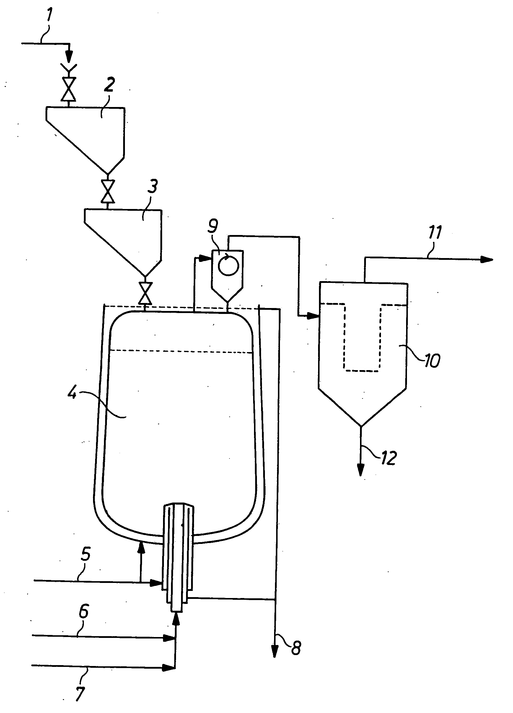
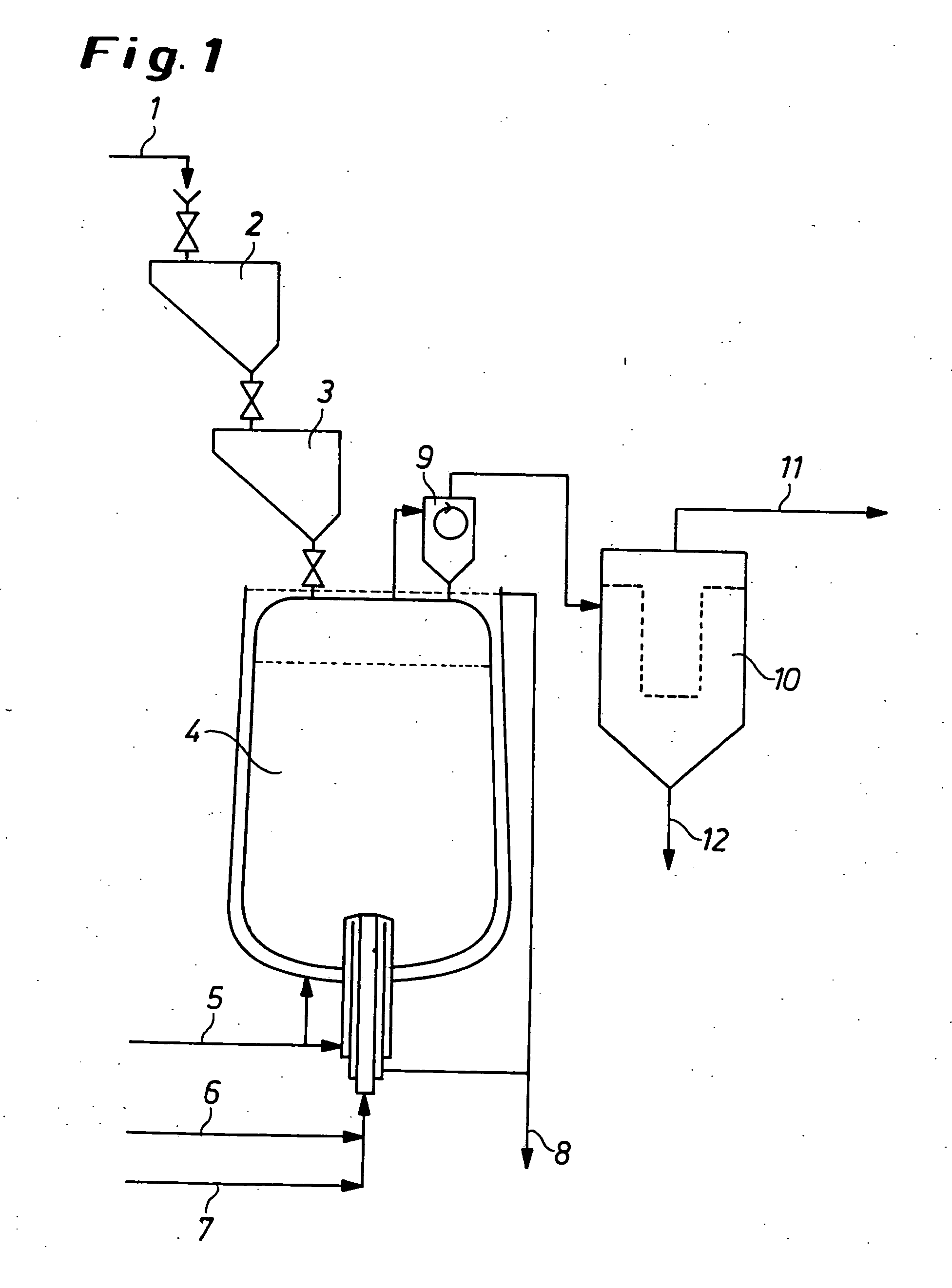
[0036] The present invention provides a generator comprising [0037] (I) a double-chamber lock consisting of two tapered or vertical chambers lined with ceramics or plastics, as the charging device, [0038] (II) at least one tubular shaft furnace consisting of a water-cooled double jacket of steel, [0039] (III) a double-walled, water-cooled inlet nozzle of pure copper for the gasification mixture, arranged centrally in the tubular shaft furnace just above the base, [0040] (IV) a dust-removing device, and also [0041] (V) optionally a desulfurising d...


PUM

PropertyMeasurementUnit
Lengthaaaaaaaaaa
Fractionaaaaaaaaaa
Fractionaaaaaaaaaa

Abstract

A generator including a double-chamber lock comprising two tapered or vertical chambers lined with ceramics or plastics, as a charging device, at least one tubular shaft furnace comprising a water-cooled double jacket of steel, a double-walled, water-cooled inlet nozzle of copper for a gasification mixture, arranged centrally in the tubular shaft furnace above the base, a dry dust-removing device, and optionally a desulfurising device. The double-chamber lock has a mechanism which causes one of the chambers to open when the lower chamber of the double-chamber lock is flushed with inert gas after charging/opening operations, and the inlet nozzle constitutes the mixing member for the constituents of the gasification mixture, the inlet nozzle has a radius of curvature of the surface of the cylindrical portion of the nozzle which continuously becomes smaller to the outlet opening, and the direction of flow of the gases leaving the inlet nozzle is directed upwards.

Description

CROSS REFERENCE TO RELATED PATENT APPLICATION [0001] The present patent application claims the right of priority under 35 U.S.C. §119 (a)-(d) of German Patent Application No. 103 48 116.8, filed Oct. 16, 2003. BACKGROUND OF THE INVENTION [0002] 1. Field of the Invention [0003] The present invention relates to a novel generator for the reaction of carbon-containing raw materials and also to an improved process for the production of carbon monoxide gas (CO gas) having a high degree of purity using such a generator. [0004] 2. Description of the Prior Art [0005] Carbon monoxide gas is frequently produced in the art by means of a continuous process in which carbon-containing raw materials are reacted with oxygen and carbon dioxide at relatively high temperatures using the Boudouard equilibrium. [0006] The principle of a vertical shaft furnace for such thermal processes has been known for a long time from metallurgy and is described, for example, in “Lueger, Lexikon der Technik, Vol. 16 (...

Claims


Application Information

Patent Timeline
IPC IPC(8): C01B32/40C01B32/60C10J3/20C10J3/48C10J3/76C21B11/00C21B13/00C21B15/00
CPCC10J3/485C10J3/76C10J2200/156C10J2300/1807C10J2300/0969C10J2300/0973C10J2300/0959
Inventor BLASCHKE, HERBERTBREUER, WERNERKOHLER, KARL-HEINZUNGERECHTS, HERBERT
Owner BAYER MATERIALSCIENCE AG
Why Eureka
Try Eureka