
Ship motion predictor

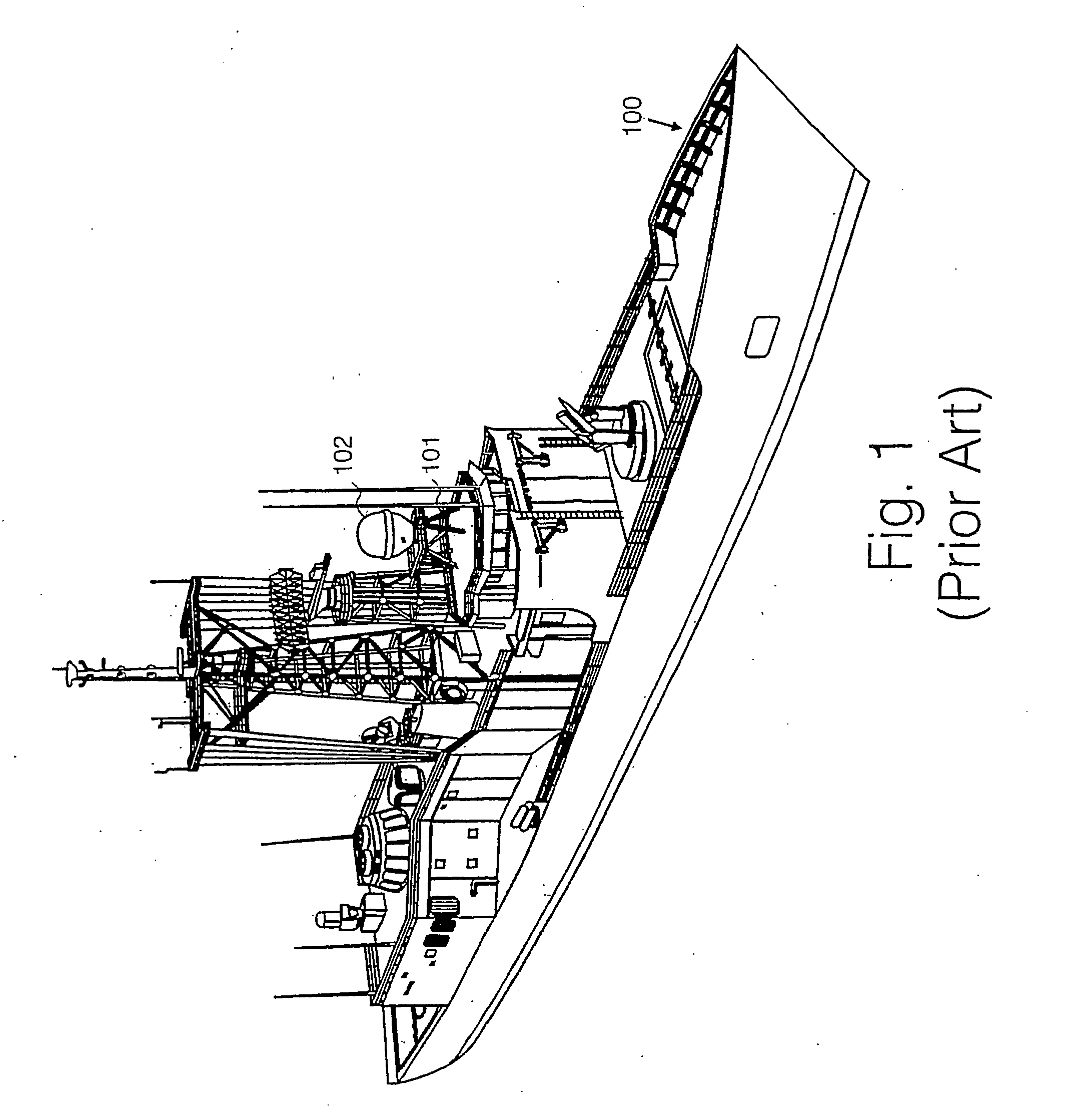
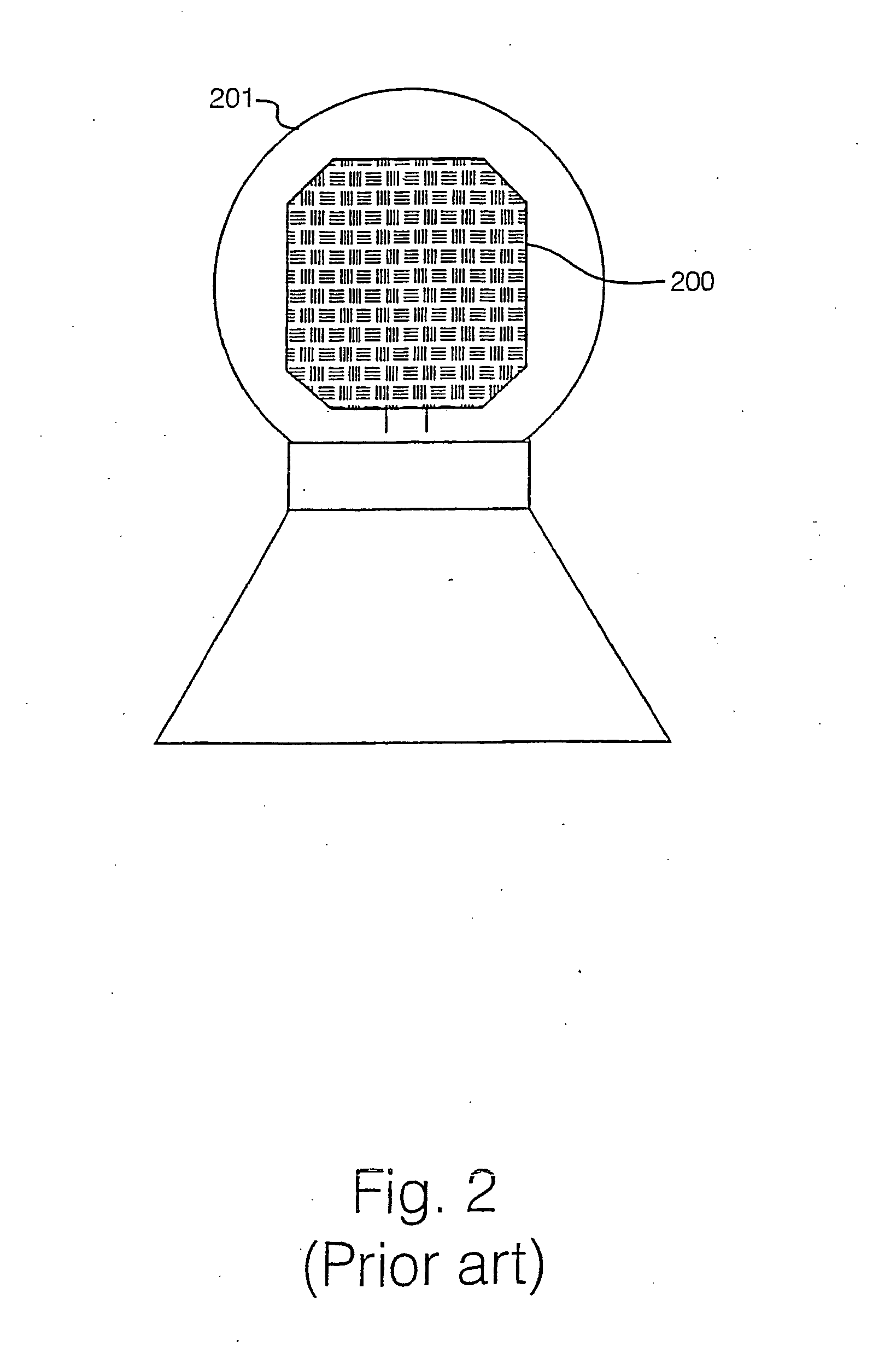
a technology of motion prediction and ship, applied in the direction of positioning/direction control, navigational aid arrangement, reradiation, etc., can solve the problems of not being able to mechanically stabilize the radar, the particular problem of predicting the look direction of the antenna is not well addressed

Active Publication Date: 2005-05-12
BAE SYSTEMS PLC
View PDF6 Cites 24 Cited by
  • Summary
  • Abstract
  • Description
  • Claims
  • Application Information

AI Technical Summary

Benefits of technology

The present invention provides a method and apparatus for predicting the position and orientation of a vessel or a rotating antenna mounted on a vessel. The method involves inputting data on the vessel's position, pitch, and heading, and applying a moving time window sample to obtain a time moving average of the data. The data is then filtered to remove any offset data, and an auto-regression process is applied to the data to predict the future movement of the vessel or antenna. The predicted angles of movement are then stored as a set of rotation matrix data. The apparatus includes a roll data generator, pitch data generator, and heading data generator, as well as filters and an auto-regressor for applying the method. The technical effects of the invention include improved prediction of the vessel's position and orientation, assistance in stabilizing sensors and weapons on the vessel, and assistance in landing aircraft on the vessel.

Problems solved by technology

Typically, in some circumstances, some radars cannot be mechanically stabilized, because a stabilizer is too heavy and too expensive on top of a main mast of a typical ship.
It takes time to point a radar beam in relation to the antenna axes, and “looks” can only be executed during future windows of visibility.
However, much of the prior art literature addresses the problem of predicting the orientation of an air craft carrier in order to assist air craft landings.
The particular problems of prediction of an antenna look direction are not well addressed in the prior art.
However, as the ship rolls and pitches in rougher sea, the superstructure sways around.
Where for example the radar is used for location of incoming air craft, unless the movement of the ship relative to the sea's surface is corrected for, the radar can give misleading positioning of incoming aircraft, having a wide range of fluctuation of bearing from the ship.
Prior art algorithms for antenna look direction prediction are generally not successful, and all evoke a “modeling” principle.
Prior art models of this kind are inflexible as well as complicated to set up.
Also, some of the effects of the prior art prediction models are speed dependent.

Method used


Image

  • Ship motion predictor
  • Ship motion predictor
  • Ship motion predictor

Examples


Embodiment Construction

[0102] There will now be described by way of example the best mode contemplated by the inventor for carrying out the invention. In the following description numerous specific details are set forth in order to provide a thorough understanding of the present invention. It will be apparent however, to one skilled in the art, that the present invention may be practiced without limitation to these specific details. In other instances, well known methods and structures have not been described in detail so as not to unnecessarily obscure the present invention.

[0103] Whilst in the following description, a best mode implementation is described with respect to a ship's radar, the methods and apparatus disclosed are not restricted to a ship's radar but may be applied to any rotating antenna of any type of vehicle and the scope of the invention is limited only by the wording of the claims herein.

[0104] In this specification, the term “pitch” is used to mean rotation of a ship about a transver...


PUM


Abstract

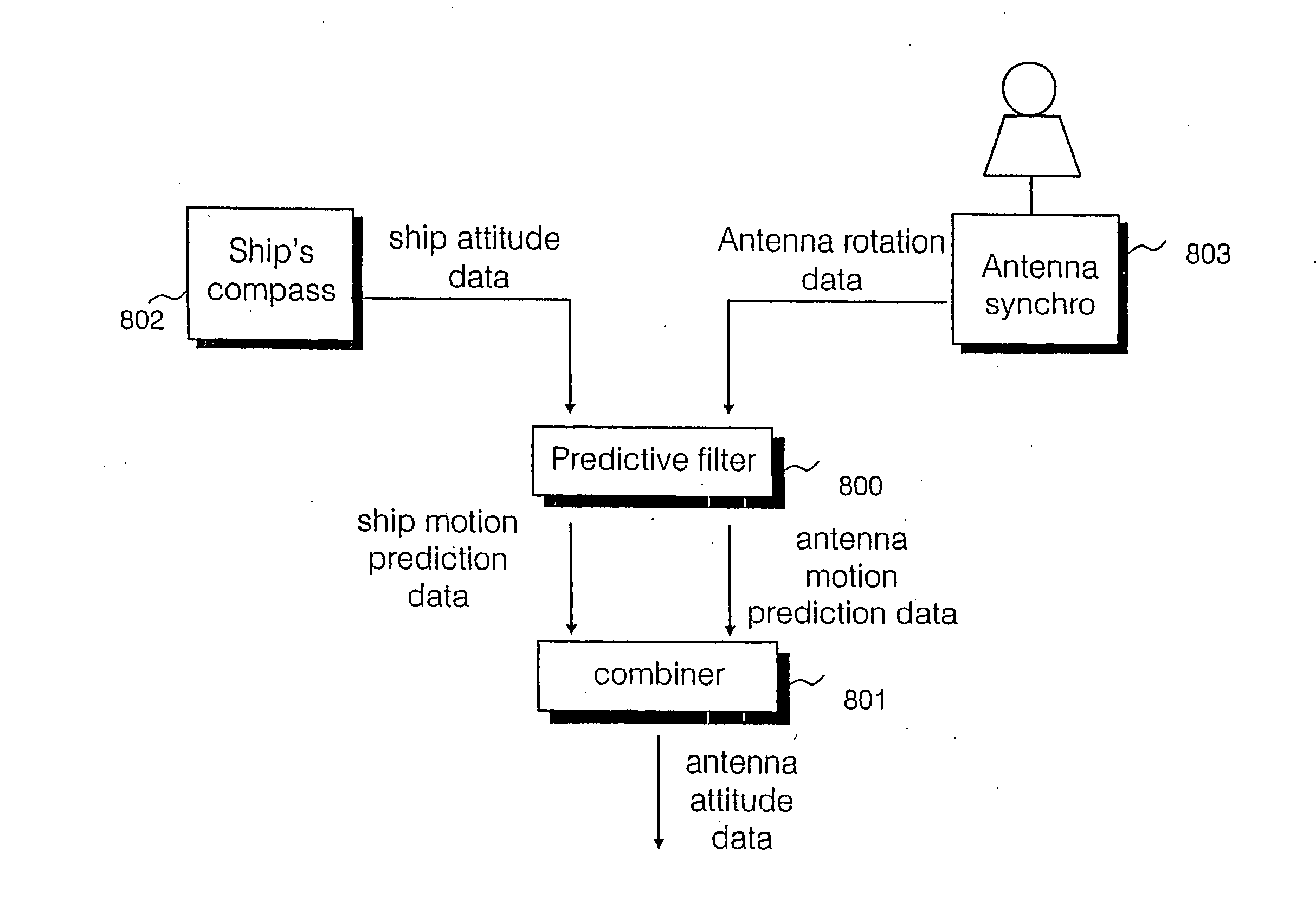
There is disclosed a predictive filter for predicting the future position of a look direction of a rotating directional antenna mounted on a vessel. Prediction of a look direction of the antenna at any instant is made from input of ship's compass data including roll data, pitch data and heading data, as well as data describing a rotational position of the antenna, output from an antenna synchro device. Smoothing of the digital roll, pitch and heading data and antenna position data is followed by application of a moving time window, filter which removes any offset from the data within of the moving time window to produce data having a zero mean. The zero mean data is input into an auto-regression algorithm, the output of which is combined with mean roll, pitch, heading, position and antenna velocity data to obtain predicted positions of the antenna relative to the vessel, and a predicted motion of the vessel. The combined vessel motion prediction and antenna position and velocity prediction can be used to establish a predictive future look direction of the antenna for a period of between 0.1 and 5 seconds into the future.

Description

FIELD OF THE INVENTION [0001] The present invention relates to motion prediction for a vehicle, particularly, but not exclusively a marine vessel. BACKGROUND TO THE INVENTION [0002] Sea going vessels, particularly ships, are fitted with radar early warning systems which warn of approaching vehicles, including aircraft and surface vessels, within a range of the ship's radar. The radar needs to accurately establish the position of vehicles within the radar range relative to the ship in three dimensions. Typically, in some circumstances, some radars cannot be mechanically stabilized, because a stabilizer is too heavy and too expensive on top of a main mast of a typical ship. [0003] Typically, the positions of vehicles are determined along a “look” of the radar. Such a look comprises a radar transmission along a particular direction in space relative to the ship. Each direction is defined by angles with respect to a central axis of a radar antenna. Therefore, to determine the direction ...

Claims


Application Information

Patent Timeline
Patent Type & Authority Applications(United States)
IPC IPC(8): B63B39/14B63B49/00G01S7/40G01S13/02G01S13/86H01Q1/18
CPCB63B39/14B63B49/00H01Q1/18G01S13/86G01S2013/0272G01S7/4004
Inventor DEAKIN, ANTHONY MICHAEL
Owner BAE SYSTEMS PLC
Learn More