Dual loop exhaust gas recirculation system for diesel engines and method of operation

a diesel engine and exhaust gas technology, applied in the direction of machines/engines, mechanical equipment, non-fuel substance addition to fuel, etc., can solve the problems of no longer containing a great amount of excess oxygen, nox and soot emissions from stationary and mobile diesel engines, and contributing to air pollution

Active Publication Date: 2005-05-19
SOUTHWEST RES INST
View PDF10 Cites 33 Cited by
  • Summary
  • Abstract
  • Description
  • Claims
  • Application Information

AI Technical Summary

Benefits of technology

[0009] Another feature of the dual loop exhaust gas recirculation system for a Diesel engine, in accordance with the present invention, includes an intercooler interposed between the discharge port of the compressor stage of the turbocharger and the intake manifold of the engine. Desirably, the intercooler is adapted to selectively bypass at least a portion of fluid discharged from the discharge port of the compressor stage around a heat transfer portion of the intercooler and into the intake manifold of the engine without significantly altering the temperature of the bypassed fluid.

Problems solved by technology

However, NOx and soot emissions from both stationary and mobile Diesel engines are a major contributor to air pollution.
These gases have already been used by the engine and no longer contain a great amount of excess oxygen.
However, if the combustion temperature is too low, combustion becomes unstable, resulting in the formation of soot, i.e., particulate matter (PM), an undesirable emission.
However, the Weisman, et al. system cannot control combustion temperatures independently of exhaust gas recirculation flow rate.

Method used


Image

  • Dual loop exhaust gas recirculation system for diesel engines and method of operation
  • Dual loop exhaust gas recirculation system for diesel engines and method of operation
  • Dual loop exhaust gas recirculation system for diesel engines and method of operation

Examples


Embodiment Construction

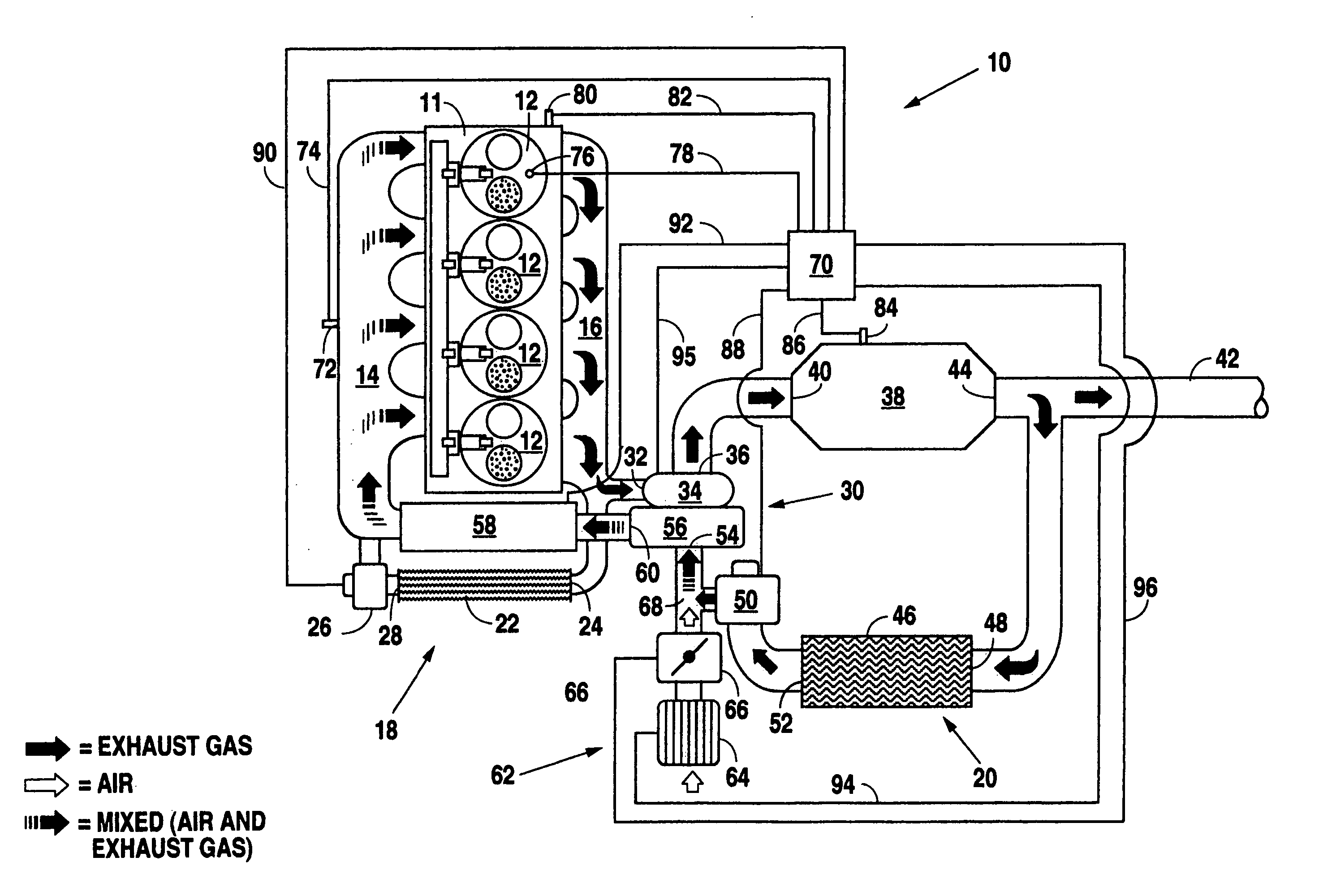
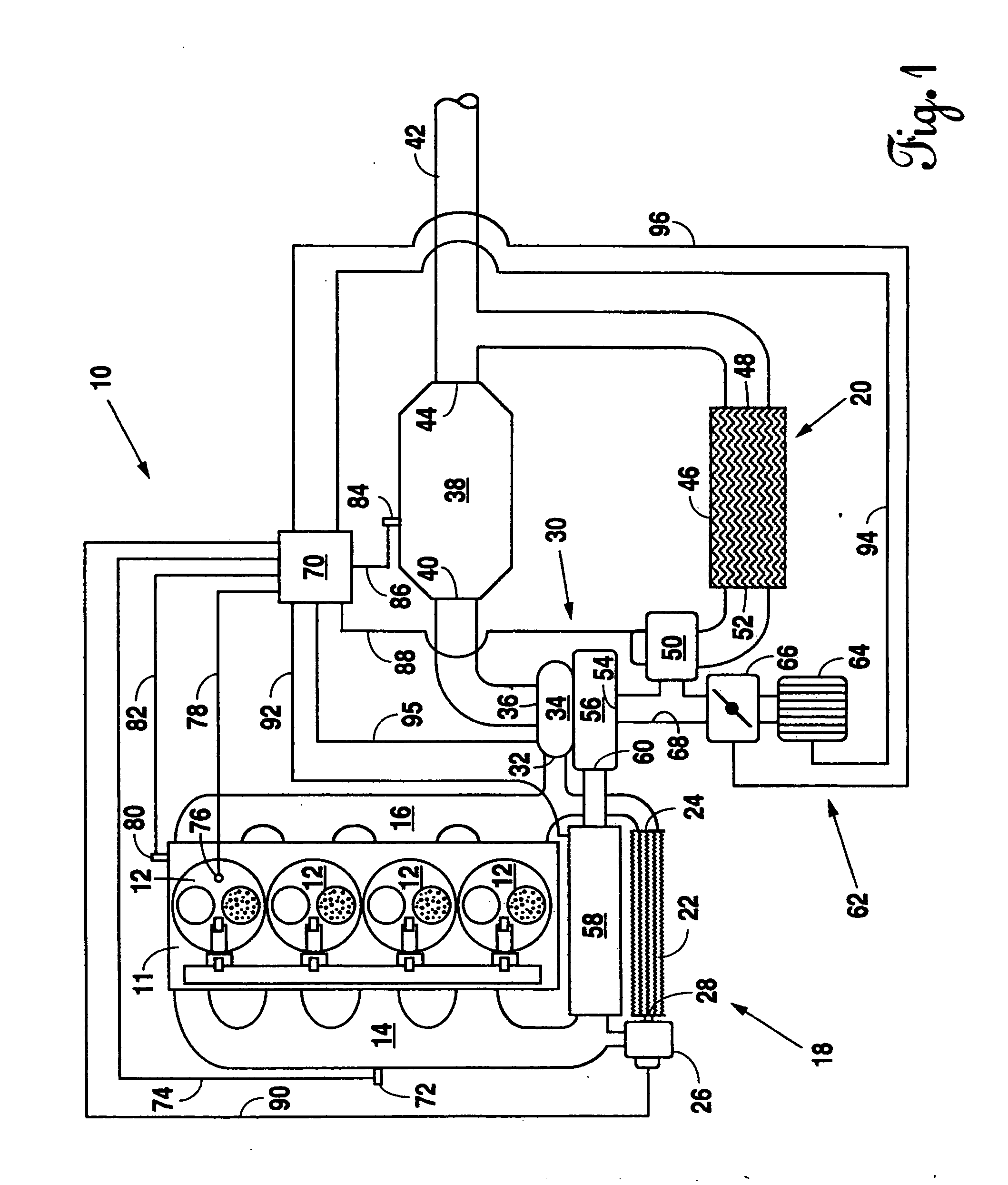
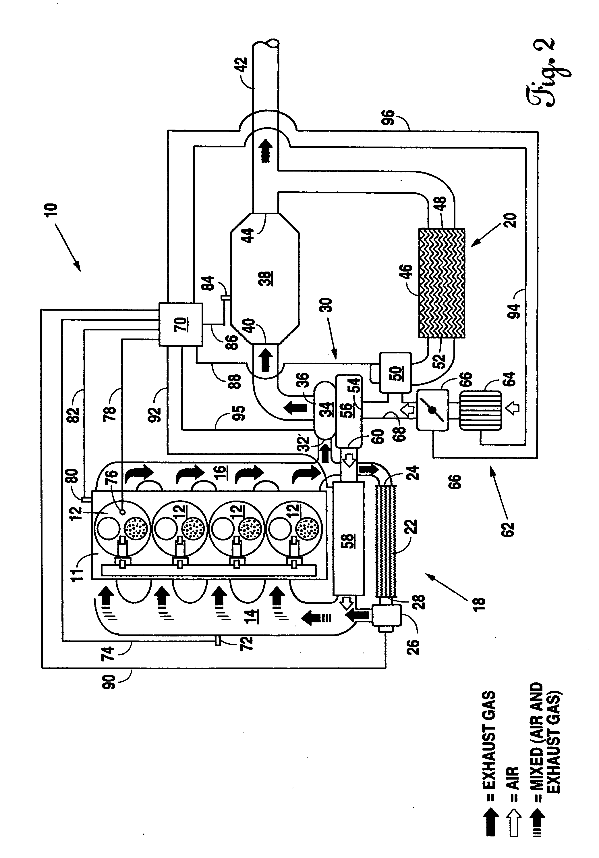
[0020] A dual loop exhaust gas recirculation system for a Diesel engine is generally indicated with reference numeral 10 in FIG. 1. The Diesel engine has at least one, and in the illustrated example four, combustion chambers 12, an intake manifold 14, and an exhaust manifold 16, both in respective communication with combustion chambers 12. The dual loop exhaust gas recirculation 10, in accordance with the present invention, has a high pressure exhaust gas recirculation loop 18 and a low pressure exhaust gas recirculation loop 20. The high pressure exhaust gas recirculation loop 18 has an oxidation catalyst 22 with an intake port 24 is in controlled fluid communication with the exhaust manifold 16 of the engine. The oxidation catalyst 22 reduces carbon monoxide (CO) and unburned hydrocarbons (HC) thereby reduces the unburned hydrocarbons, and in the process, consumes oxygen (O2). Reducing the hydrocarbons carried in the exhaust gases discharged from the exhaust manifold 16 greatly re...


PUM


Abstract

A catalyst bed temperature of an aftertreatment device is maintained and the operational regime for stable and smokeless rich combustion is expanded by use of a dual loop exhaust gas recirculation system. Under light load conditions, at least a portion of the exhaust gas is recirculated through a relatively high pressure exhaust gas recirculation loop, wherein there is no substantial reduction in recirculated exhaust gas temperature or pressure. When operating in relatively medium or higher load operating regimes of the engine, at least a portion of the exhaust gas is passed through a relatively low pressure recirculation mode in which work is extracted from the recirculated gas by the turbine stage of a turbocharger and an exhaust gas recirculation cooler prior to reintroduction into the intake manifold of the engine.

Description

BACKGROUND OF THE INVENTION [0001] 1. Technical Field [0002] This invention relates generally to exhaust gas recirculation systems and methods of operation and more particularly to such systems and methods applicable to Diesel engines. [0003] 2. Background Art [0004] Diesel engines play an important role in power generation and transportation economies. However, NOx and soot emissions from both stationary and mobile Diesel engines are a major contributor to air pollution. In order to meet future NOx emissions requirements, heavy-duty Diesel engines are looking to utilize exhaust gas recirculation (EGR) technology as a means of lowering NOx emissions. This technique directs some of the exhaust gases back into the intake of the engine. These gases have already been used by the engine and no longer contain a great amount of excess oxygen. By mixing the exhaust gases with fresh air, the amount of oxygen entering the engine is reduced. Since there is less oxygen to react with, few nitrog...

Claims


Application Information

Patent Timeline
Patent Type & Authority Applications(United States)
IPC IPC(8): F01N3/08F02B37/18F02B37/24F02M25/07
CPCF01N3/0821F01N3/0842F02B29/0418F02B29/0425F02B29/0437F02B37/18Y02T10/144F02M25/0707F02M25/0709F02M25/0718F02M25/0727F02M25/074Y02T10/121F02B37/24F02M26/05F02M26/06F02M26/15F02M26/23F02M26/35Y02T10/12
Inventor SASAKI, SHIZUO
Owner SOUTHWEST RES INST
Why Eureka
Try Eureka