Wideband light source

Inactive Publication Date: 2005-05-19
SAMSUNG ELECTRONICS CO LTD
View PDF5 Cites 9 Cited by
  • Summary
  • Abstract
  • Description
  • Claims
  • Application Information

AI Technical Summary

Benefits of technology

[0018] An object of the present invention is to provide a wideband light source capable of easily controlling the output of spontaneous emission light of different wavelengths and outputting spontaneous emission light in high-power. In order to accomplish the above object of the invention, there is provided a wideband light source including a first optical amplifier for generating and amplifying a C-band spontaneous emission light, a second optical amplifier for generating C-ban

Problems solved by technology

However, the conventional wideband light source having the first isolator arranged between the first and second amplifying media produces lower amplification efficiency and does not utili

Method used


Image

  • Wideband light source
  • Wideband light source
  • Wideband light source

Examples


first embodiment

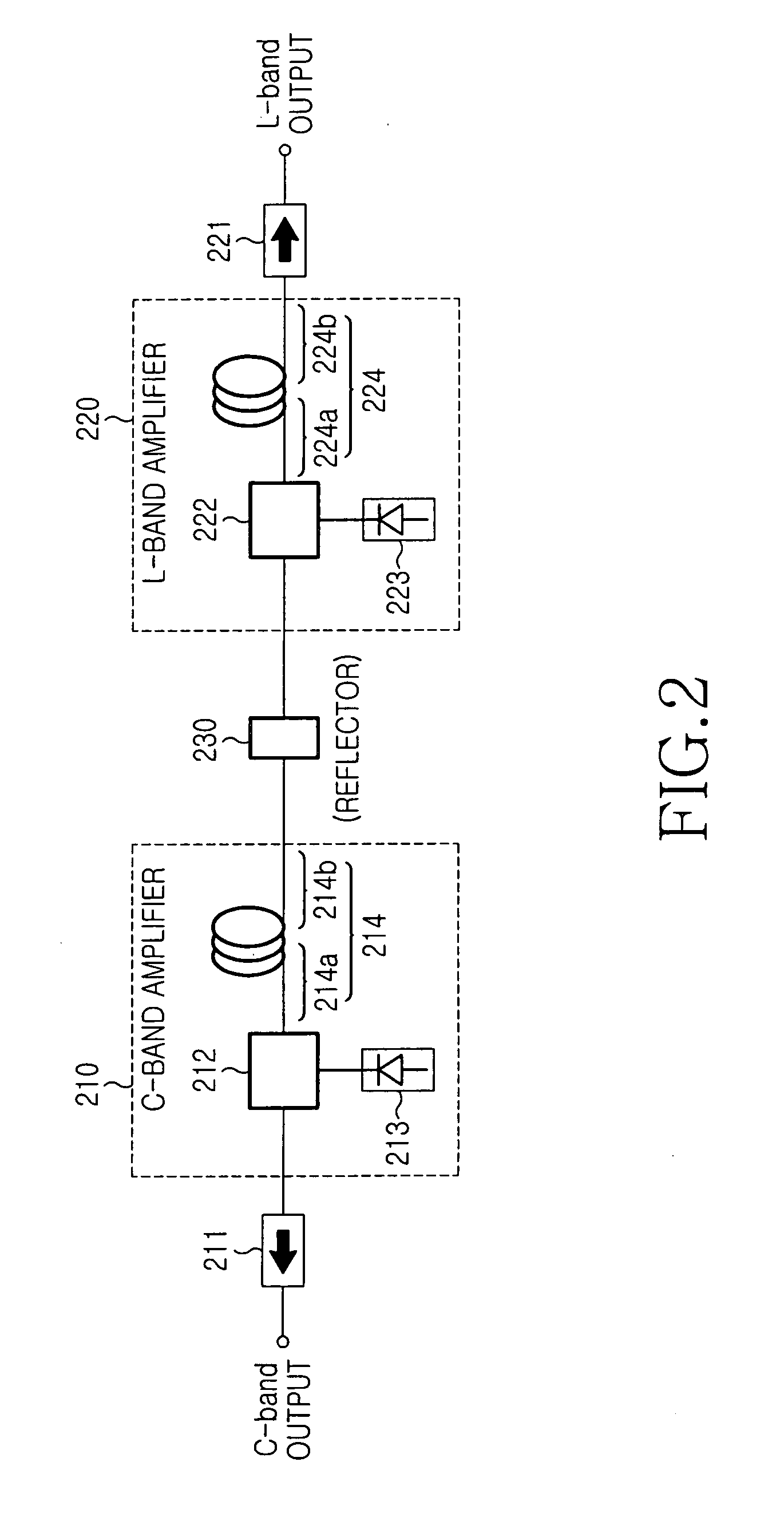
[0027]FIG. 2 shows the construction of a wideband light source according to the present invention. As shown, the wideband light source includes a first optical amplifier 210 for generating spontaneous emission light in the C-band, a second optical amplifier 220 for generating spontaneous emission light in the L-band, a reflector 230 positioned between the first and second optical amplifiers 210 and 220, a first isolator 211 and a second isolator 221.

[0028] The first optical amplifier 210 includes a first amplifying medium 214 for generating and amplifying spontaneous emission light in the C-band, a first pump light source 213 and a first optical coupler 212. The first optical amplifier 210 generates and amplifies C-band spontaneous emission light and outputs the amplified spontaneous emission light to the first isolator 211.

[0029] The first amplifying medium 214 generates spontaneous emission light in the C-band and outputs the generated light to first and second ends 214a and 214b...

second embodiment

[0042]FIG. 3 shows the construction of a wideband light source according to the present invention. As shown, the wideband light source includes a first optical amplifier 310 for generating spontaneous emission light in the C-band, a second optical amplifier 320 for generating spontaneous emission light in the L-band, a reflector 330 positioned between the first and second optical amplifiers 310 and 320, a first isolator 311 and a second isolator 321.

[0043] The reflector 330 is positioned between the first and second optical amplifiers 310 and 320 in order to reflect the C-band spontaneous emission light generated from the first optical amplifier 310 back to the first optical amplifier 310 and the C-band and L-band spontaneous emission lights generated from the second optical amplifier 320 back to the second optical amplifier 320.

[0044] The first optical amplifier 310 includes a first amplifying medium 314 for generating and amplifying spontaneous emission light in the C-band, a fir...

third embodiment

[0051]FIG. 4 shows the construction of a wideband light source according to the present invention. As shown, the wideband light source includes a first optical amplifier 410 for generating and amplifying spontaneous emission light in the C-band, a second optical amplifier 420 for generating and amplifying spontaneous emission light in the L-band and a reflector 430.

[0052] The reflector 430 includes an optical fiber reflector 431 and a C-band filter 432. The C-band filter 432 is positioned between the optical fiber reflector 431 and the first optical amplifier 410 in order to limit the bandwidth of the C-band spontaneous emission light inputted to the optical fiber reflector 431 and reflected by the optical fiber reflector 431.

[0053] The optical fiber reflector 431 reflects the C-band spontaneous emission light generated from the first optical amplifier 410 back to the first optical amplifier 410 and the C-band and L-band spontaneous emission lights generated from the second optical...


PUM


Abstract

A wideband light source is disclosed. The wideband light source includes a first optical amplifier for generating and amplifying a C-band spontaneous emission light, a second optical amplifier for generating C-band and L-band spontaneous emission lights which is pumped by the C-band spontaneous emission light to amplify an L-band spontaneous emission light, and a reflector positioned between the first and second optical amplifiers to reflect the C-band spontaneous emission light provided from the first optical amplifier back to the first optical amplifier and the C-band and L-band spontaneous emission lights provided from the second optical amplifier back to the second optical amplifier.

Description

CLAIM OF PRIORITY [0001] This application claims priority, pursuant to 35 U.S.C. §119, to that patent application entitled “Wideband Light Source” filed in the Korean Intellectual Property Office on Nov. 14, 2003 and assigned Ser. No. 2003-80504, the contents of which are hereby incorporated by reference. BACKGROUND OF THE INVENTION [0002] 1. Field of the Invention [0003] The present invention relates to a light source capable of emitting light over a wide wavelength range, and, more particularly, to a wideband light source using an erbium-doped fiber. [0004] 2. Description of the Related Art [0005] A wavelength division multiplexed-passive optical network (WDM-PON) includes a central office for providing communication services via a plurality of downstream optical signals having wavelengths different from each other; hereinafter, referred to as “downstream optical signals”, a plurality of subscriber units for receiving downstream optical signals from the central office and outputti...

Claims


Application Information

Patent Timeline
IPC IPC(8): H01S3/10H01S3/06H01S3/067H01S3/23
CPCH01S3/067H04B10/25H04B10/2587H04B10/50
Inventor HWANG, SEONG-TAEKSHIM, CHANG-SUPOH, YUN-JE
Owner SAMSUNG ELECTRONICS CO LTD
Why Eureka
Try Eureka