Optical pickup apparatus

a technology of optical pickup and optical pickup head, which is applied in the direction of optical recording head, data recording, instruments, etc., can solve the problems of high cost or adverse influence of the apparatus, the capability of appropriately recording/reproducing information on/from such high-density dvds cannot be sufficiently increased, and the problem of high-speed recording, etc., to achieve the effect of increasing the light utilization efficiency

Inactive Publication Date: 2005-05-19
KONICA MINOLTA OPTO
View PDF7 Cites 20 Cited by
  • Summary
  • Abstract
  • Description
  • Claims
  • Application Information

AI Technical Summary

Benefits of technology

[0013] The present invention has been made in consideration of the above-described problems of the prior art, ...

Problems solved by technology

However, this may lead to a high cost or an adverse influence on the apparatus due to an increase of heat generation.
The capability of appropriately recording/reproducing information on/from such high-density DVDs cannot sufficiently increase the value of optical pickup apparatuses as products yet.
Accordingly...

Method used


Image

  • Optical pickup apparatus
  • Optical pickup apparatus
  • Optical pickup apparatus

Examples


first embodiment

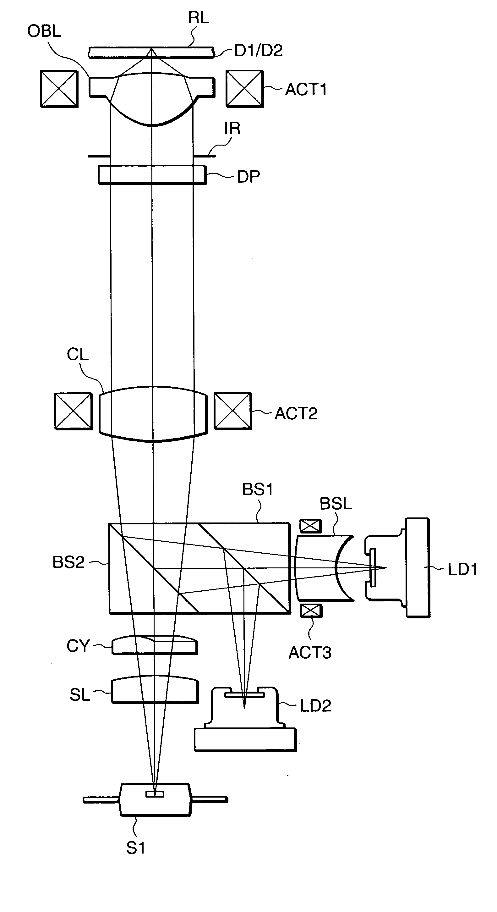
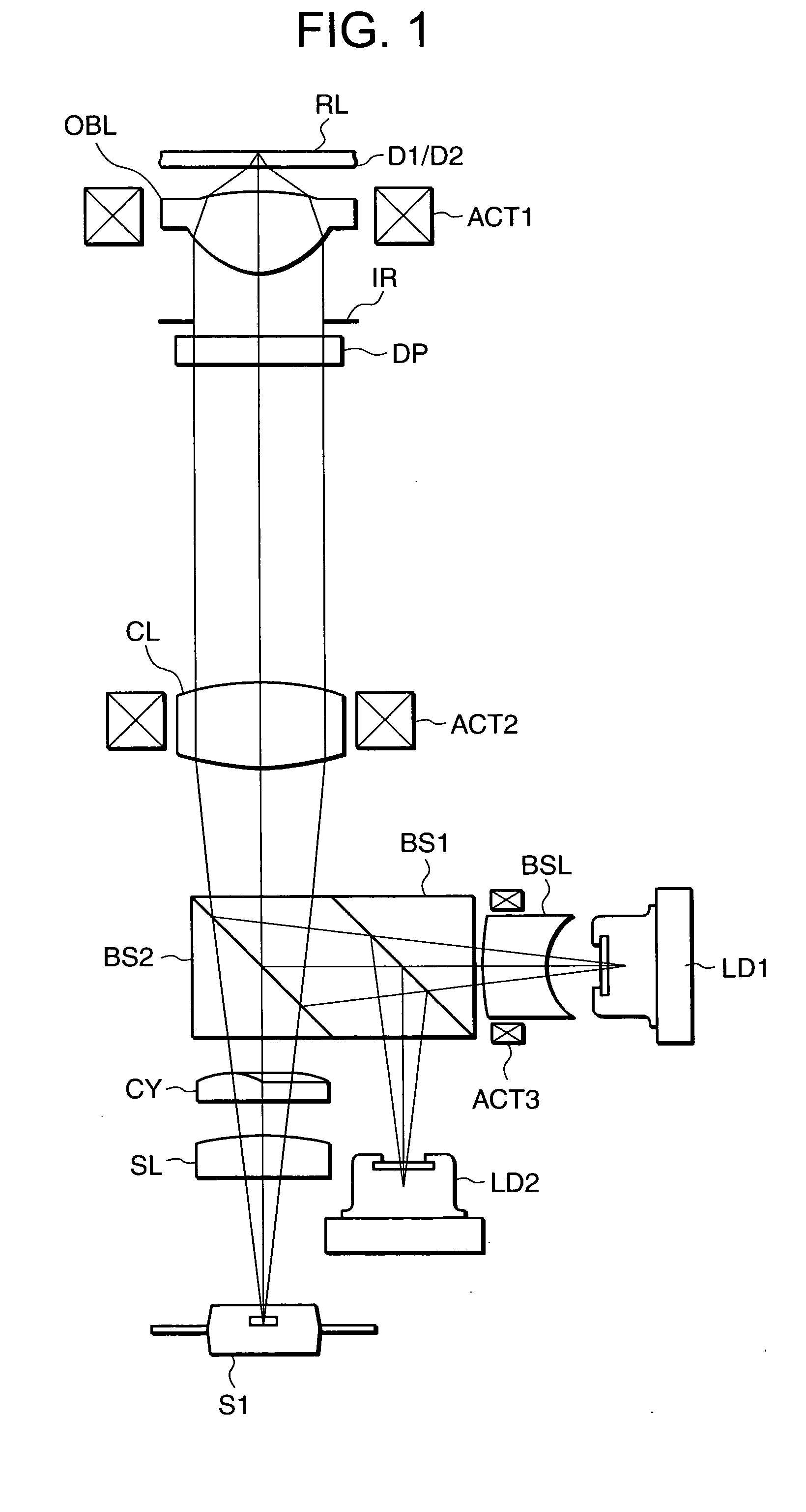
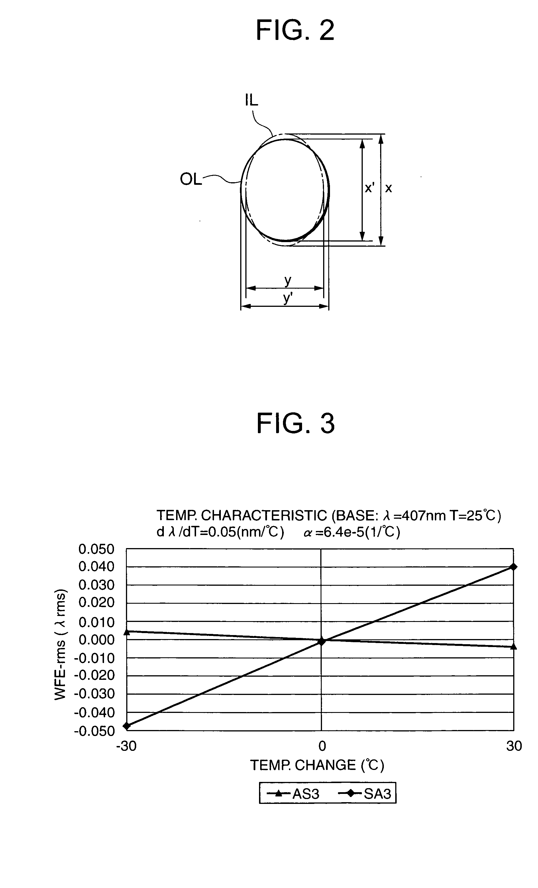
[0038]FIG. 1 is a view schematically showing the overall arrangement of an optical pickup apparatus according to the present invention. This optical pickup apparatus can record / reproduce information on / from both a high-density DVD (to be also referred to as a first optical disk D1) and a conventional DVD (to be also referred to as a second optical disk D2). FIG. 2 is a view showing a crass-section of a light beam which enters a beam shaping lens BSL serving as a beam shaping element and a crass-section of a light beam which exits from the beam shaping lens in a direction perpendicular to the optical axis.

[0039] Referring to FIG. 1, a divergent light beam emitted from a first semiconductor laser LD1 (wavelength λ1=380 to 430 nm; 407 nm in this embodiment) serving as a first light source enters the beam shaping lens BSL first. As shown in FIG. 2, a light beam IL which has entered the beam shaping lens BSL has an almost elliptical cross-section formed by tracing points with an intensit...

second embodiment

[0067]FIG. 6 is a view schematically showing the overall arrangement of an optical pickup apparatus according to the present invention. In FIG. 6, the same reference numerals and symbols as in FIG. 1 denote constituent elements having the same functions and effects as in FIG. 1.

[0068] In the second embodiment shown in FIG. 6, in addition to first and second semiconductor lasers LD1 and LD2, an infrared semiconductor laser LD3 (wavelength λ3=790 nm) which is mainly used to record / reproduce information on / from a commercially available CD (third optical disk D3) is incorporated as a third light source.

[0069] In the example shown in FIG. 6, the second light source LD2 and third light source LD3 are integrated by a light source unit LU23. Hence, in the second embodiment, two beam splitters, i.e., a beam splitter BS1 used for a light beam emitted from the first light source and a beam splitter BS2 used for a light beam emitted from the second or third light source are arranged.

[0070] In...

third embodiment

[0072]FIG. 7 is a view schematically showing the overall arrangement of an optical pickup apparatus according to the present invention. In FIG. 7, the same reference numerals and symbols as in FIG. 1 denote constituent elements having the same functions and effects as in FIG. 1.

[0073] In the third embodiment shown in FIG. 7, three light sources, i.e., first to third light sources LD1, LD2, and LD3 are arranged independently. Hence, beam splitters are arranged respectively in the optical paths through which light beams emitted from the light sources pass. HOE in FIG. 7 indicates a hologram element such as a prism having a polarizing function.


PUM


Abstract

This invention provides an optical pickup apparatus which includes a plurality of light sources, a beam shaping element which is arranged in an optical path through which a light beam emitted from at least one of the light sources passes, and an optical system which includes a divergence angle conversion element and an objective lens and is arranged in an optical path through which the light beams emitted from the plurality of light sources pass, and records and/or reproduces information by condensing, through the objective lens, the light beam emitted from each light source on the information recording surface of a corresponding optical information recording medium. An almost elliptical cross-sectional shape of the light beam which enters the beam shaping element is shaped into a cross-sectional shape closer to an almost circular shape or a circular shape, and the light beam emerges from the beam shaping element. The light beam which enters the divergence angle conversion element emerges from it with a reduced angle or degree of divergence.

Description

FIELD OF THE INVENTION [0001] The present invention relates to an optical pickup apparatus and, more particularly, to a compatible optical pickup apparatus which can record and / or reproduce information on / from at least two different optical information recording media by using light beams emitted from a plurality of light sources having different light source wavelengths. BACKGROUND OF THE INVENTION [0002] In recent years, high-power DVD laser diodes have been developed so that a write on DVDs is possible. [0003] As one method for high-speed recording on DVDs, the light amount is increased by using a high-power light source. More specifically, when the output of a semiconductor laser (laser diode) serving as a light source is raised, the light amount can be increased. However, this may lead to a high cost or an adverse influence on the apparatus due to an increase of heat generation. [0004] As a method for increasing the light utilization efficiency without making the light source p...

Claims


Application Information

Patent Timeline
IPC IPC(8): G11B7/00
CPCG11B7/1356G11B7/1376G11B2007/0006G11B7/13927G11B7/1398G11B7/1378
Inventor SAKAMOTO, KATSUYAHASHIMURA, JUNJIIKENAKA, KIYONO
Owner KONICA MINOLTA OPTO
Why Eureka
Try Eureka