Hydrogen cartridge, fuel cell system and method of attaching hydrogen cartridge

a fuel cell and cartridge technology, applied in electrochemical generators, transportation and packaging, cellular phones, etc., can solve the problems of hydrogen gas handling problems, hydrogen may remain without diffusion, and increase the degree of freedom in the layout of the inside of the casing of the electronic device, increase the degree of freedom of electronic device casing layout, and prevent hydrogen leakage

Inactive Publication Date: 2005-05-19
CANON KK
View PDF10 Cites 23 Cited by
  • Summary
  • Abstract
  • Description
  • Claims
  • Application Information

AI Technical Summary

Benefits of technology

[0025] With the present invention, after confirming that the hydrogen cartridge is normally connected to the fuel cell body, the movable part or the hydrogen storage chamber can be operated to supply hydrogen. Further, after operating the movable part or the hydrogen storage chamber to stop the hydrogen supply, the hydrogen cartridge can be detached from the fuel cell body. Therefore, when the hydrogen cartridge is attached to or detached from the fuel cell body, leakage of hydrogen due to unstable connection between the hydrogen cartridge and the fuel cell body can be prevented, so that a hydrogen cartridge is provided which can be handled with safety.
[0026] Further, when the hydrogen cartridge of the present invention has the configuration in which either the movable part or the hydrogen storage chamber is folded with respect to the other, even the hydrogen cartridge requiring size reduction enough to be installed in a portable small electronic device can be attached to and detached from the fuel cell body conveniently by human hands, which can prevent leakage of hydrogen due to loose connection between the hydrogen cartridge and the fuel cell body and risks involved in the leakage. Moreover, a location at which the hydrogen cartridge is connected to the fuel cell body and a location in which the hydrogen cartridge is housed can be separately designed. Therefore, the degree of freedom in layout of the inside of a casing of an electronic device, in which the fuel cell is incorporated, can be more increased.

Problems solved by technology

In recent years, in the field of electronics, multifunctionalization and increase in amount of data to be processed in portable small electronic devices such as cellular phones, personal digital assistants (PDA), notebook personal computers, digital cameras and digital camcorder involve increased power consumption.
However, there are problems with handling of hydrogen gas.
However, in a closed system in which hydrogen is continuously leaked out from a storage container such as a tank at a small flow rate, hydrogen may remain without diffusion.
In addition, a hydrogen molecule, which is the smallest naturally occurring substance, is shielded only with difficulty and is very liable to leak out.
The leakage of hydrogen gas is liable to occur particularly when a hydrogen cartridge is connected to a fuel cell body.
Therefore, if the hydrogen cartridge is loosely connected to the fuel cell body, connection between the cartridge and the fuel cell body is kept to be unstable, thereby causing problems, in particular, increased possibility of leakage of hydrogen.
However, there are disadvantages such that the size reduction of a hydrogen cartridge makes it inconvenience to attach / detach the hydrogen cartridge to / from a fuel cell body by human hands, and possibility of leakage of hydrogen due to loose connection between the hydrogen cartridge and the fuel cell body increases.
However, considering that a hydrogen cartridge is to be installed in a small electronic device, it is preferable that unnecessary mechanisms are as less as possible.

Method used


Image

  • Hydrogen cartridge, fuel cell system and method of attaching hydrogen cartridge
  • Hydrogen cartridge, fuel cell system and method of attaching hydrogen cartridge
  • Hydrogen cartridge, fuel cell system and method of attaching hydrogen cartridge

Examples


example 1

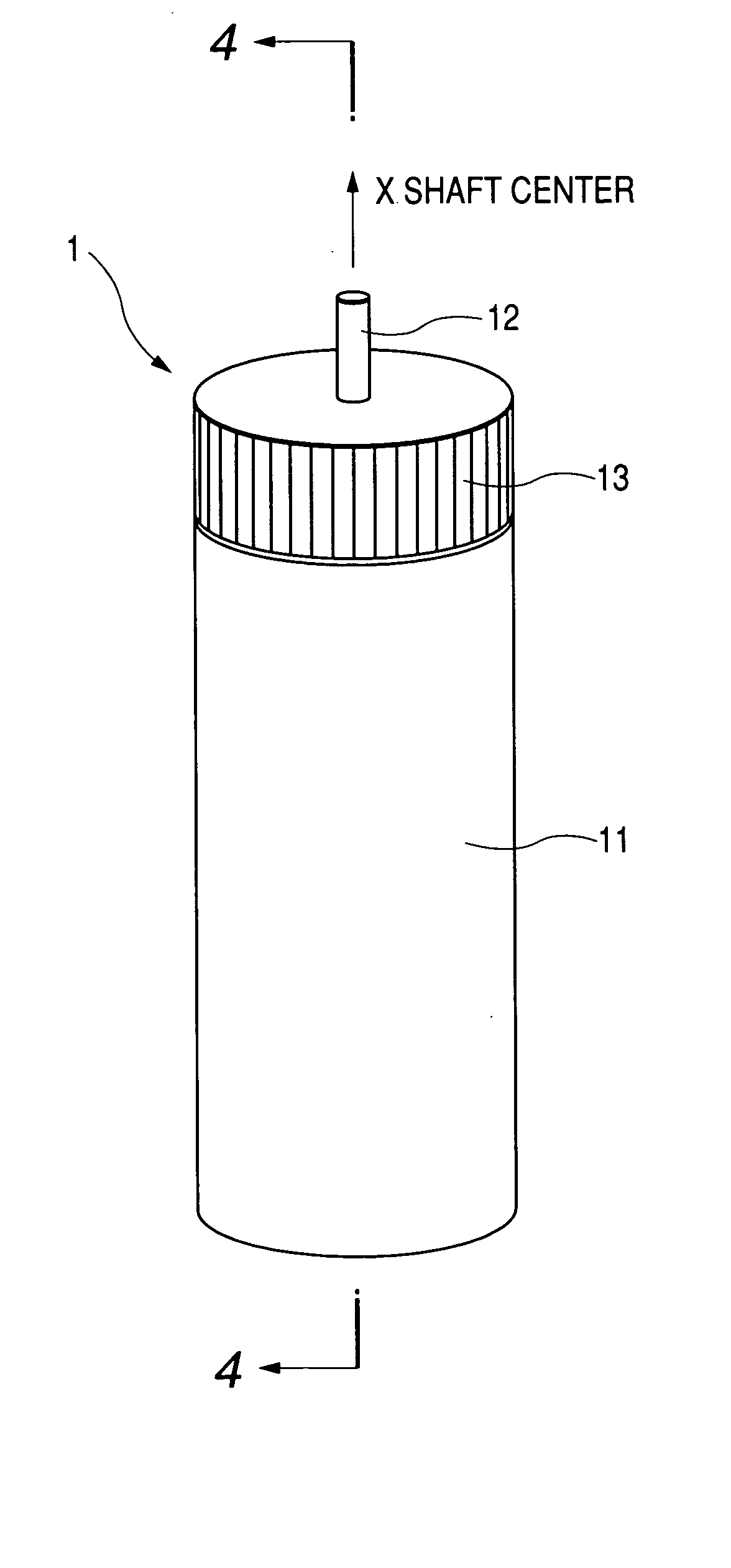
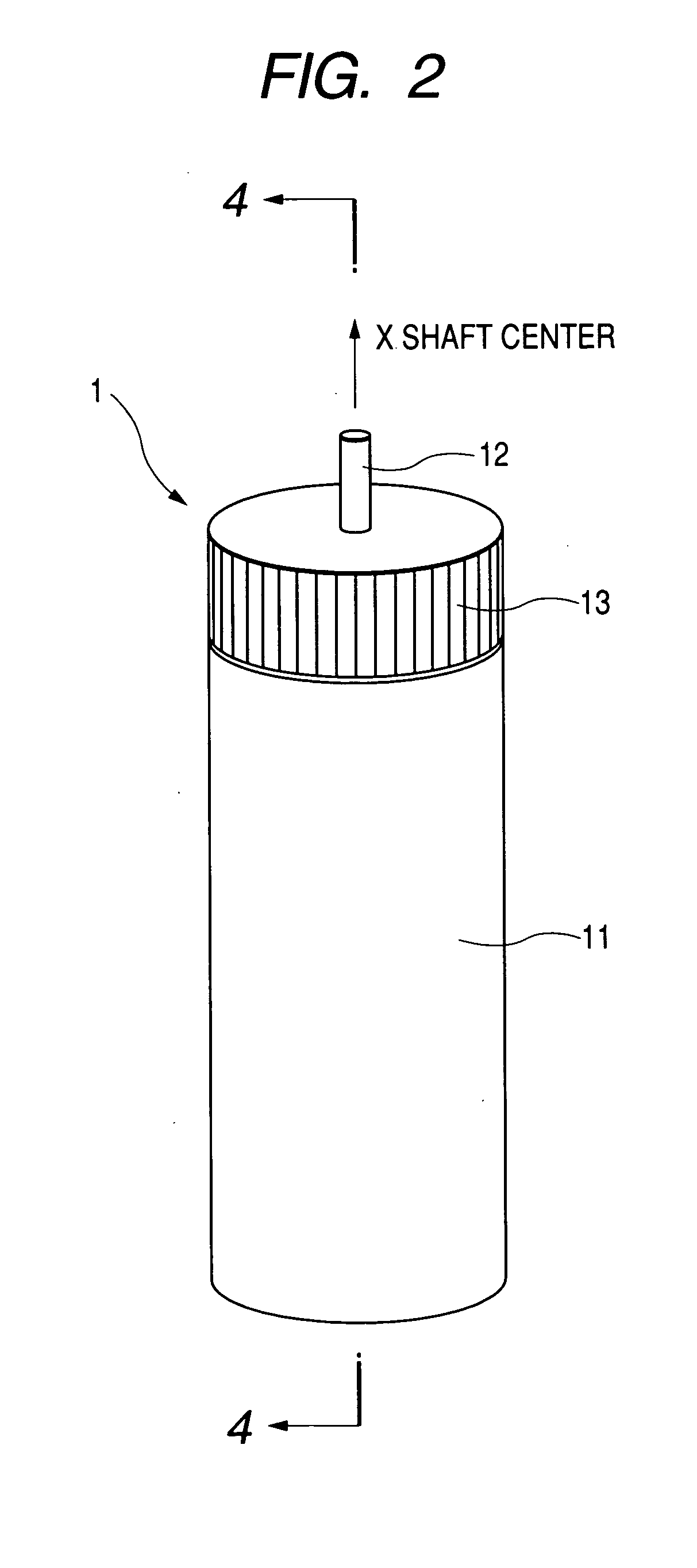
[0056]FIG. 2 is a perspective view showing a first embodiment of the hydrogen cartridge of the present invention. FIG. 3 is a partial perspective view for illustrating the movable part of the hydrogen cartridge of FIG. 2. FIG. 4A is a sectional view taken along line 4-4 in FIG. 2 for showing the hydrogen cartridge of FIG. 2 in which the hydrogen flow path is in an open state. FIG. 4B is a sectional view taken along line 4-4 for showing the hydrogen cartridge of FIG. 2 in which the hydrogen flow path is in a closed state.

[0057] As shown in the figures, a hydrogen cartridge 1 has a hydrogen storage chamber 11 for storing hydrogen, a hydrogen supply port 12 which is connected to a fuel cell body to supply hydrogen thereto, and a movable part 13 which has a hydrogen flow path 15 therein and is rotatable about an axis X parallel to the hydrogen supply port.

[0058] The hydrogen storage chamber 11 contains a hydrogen storage alloy such as LaNi5 in which hydrogen can be stored. The hydroge...

example 2

[0064]FIG. 5 is a perspective view showing a second embodiment of the hydrogen cartridge of the present invention. FIGS. 6A and 6B are partial sectional views for illustrating the movable part of the hydrogen cartridge. FIG. 6A is a partial sectional view taken along line 6-6 in FIG.5 for illustrating the movable part of the hydrogen cartridge of FIG. 5, in which the hydrogen flow path is in an open state. FIG. 6B is a partial sectional view taken along line 6-6 in FIG. 5 for illustrating the movable part of the hydrogen cartridge of FIG. 5, in which the hydrogen flow path is in a closed state.

[0065] A hydrogen cartridge 2 has a hydrogen storage chamber 21 for storing hydrogen, a hydrogen supply port 22 which is connected to a fuel cell body to supply hydrogen thereto, and a movable part 23 which can bend (or pivotally rotate) the hydrogen supply port perpendicularly within the range between a direction parallel to axis X and a direction parallel to axis Y.

[0066] The hydrogen stor...

example 3

[0071] In this example, a method for attaching the hydrogen cartridge of Example 2 to a portable small electronic device is described.

[0072]FIG. 7 is a schematic view showing an example in which the hydrogen cartridge 2 is attached to a portable small electronic device, for example, a digital camera. A portable small electronic device 3 contains a fuel cell body 31, and the fuel cell body 31 is preferably disposed on an outermost wall in a casing of the electronic device 3. A wall of the casing of the electronic device 3, on which the fuel cell body 31 is disposed, is provided with an air hole 32 for taking outside air therein, which takes oxygen used for the reaction therein.

[0073] The fuel cell body 31 is provided with a connecting part 33 for connection to a hydrogen cartridge 2. The hydrogen cartridge 2 is connected to the connecting part 33, and then perpendicularly folded upwardly to be housed in the casing of the electronic device 3. Here, since hydrogen that is lighter tha...


PUM

PropertyMeasurementUnit
thicknessaaaaaaaaaa
pressureaaaaaaaaaa
pressureaaaaaaaaaa

Abstract

There are provided a hydrogen cartridge for a fuel cell for supplying hydrogen to a fuel cell body comprising a hydrogen storage chamber for storing hydrogen, a movable part which is movably connected to the hydrogen storage chamber and has a hydrogen flow path for allowing hydrogen to flow therethrough, and a hydrogen supply port which is formed integrally with the movable part and communicates with the hydrogen flow path, wherein the cartridge takes an open state in which the hydrogen storage chamber, the hydrogen flow path and the hydrogen supply port are connected to each other, or a closed state in which the hydrogen storage chamber, the hydrogen flow path and the hydrogen supply port are not connected to each other, by movement of the movable part or the hydrogen storage chamber, and a fuel cell system having the hydrogen cartridge incorporated therein, whereby it is possible to prevent leakage of hydrogen due to unstable connection between the hydrogen cartridge and a fuel cell body and to assure safety in handling.

Description

BACKGROUND OF THE INVENTION [0001] 1. Field of the Invention [0002] The present invention relates to a hydrogen cartridge used for a fuel cell which uses hydrogen gas as a fuel, a fuel cell system using the same, and a method of attaching the hydrogen cartridge, in particular, to a hydrogen cartridge for an electronic device having a fuel cell body therein and a method of attaching the same. [0003] 2. Related Background Art [0004] In recent years, in the field of electronics, multifunctionalization and increase in amount of data to be processed in portable small electronic devices such as cellular phones, personal digital assistants (PDA), notebook personal computers, digital cameras and digital camcorder involve increased power consumption. A battery to be mounted in such a device has been strongly required to have a higher energy density and a longer service life. [0005] In the meantime, a fuel cell converts a chemical energy obtained by chemically reacting hydrogen with oxygen di...

Claims


Application Information

Patent Timeline
Patent Type & Authority Applications(United States)
IPC IPC(8): B65D85/00H01M8/04
CPCH01M8/04089Y02E60/50H01M8/04208
Inventor YAMAMOTO, JUNSHIBATA, MASAAKI
Owner CANON KK
Why Eureka
Try Eureka