Heat treatment device and heat treatment method

a heat treatment device and heat treatment technology, applied in lighting and heating apparatus, furnaces, muffle furnaces, etc., can solve the problems of obstructing the function and lowering the yield, and achieve the effect of suppressing the generation of particles and reducing the distan

Inactive Publication Date: 2005-05-19
SHIN-ETSU HANDOTAI CO LTD
View PDF4 Cites 16 Cited by
  • Summary
  • Abstract
  • Description
  • Claims
  • Application Information

AI Technical Summary

Benefits of technology

[0021] The support section of the preheat ring in this heat treatment method may be the base on which the pocket is formed, like the support section of the heat treatment apparatus of the first aspect. In this case, the preheat ring can be positioned by rotating the preheat ring placed on the base in the peripheral direction or moving the preheat ring in the pocket so as

Problems solved by technology

Occurrence of such the contact would generate a large amount of particles because the susceptor 52 and the preheat ring 53 rub each other during heat treatment, which adhere to the wafer to cause crystal defect, resulting in loweri

Method used


Image

  • Heat treatment device and heat treatment method
  • Heat treatment device and heat treatment method
  • Heat treatment device and heat treatment method

Examples


embodiment

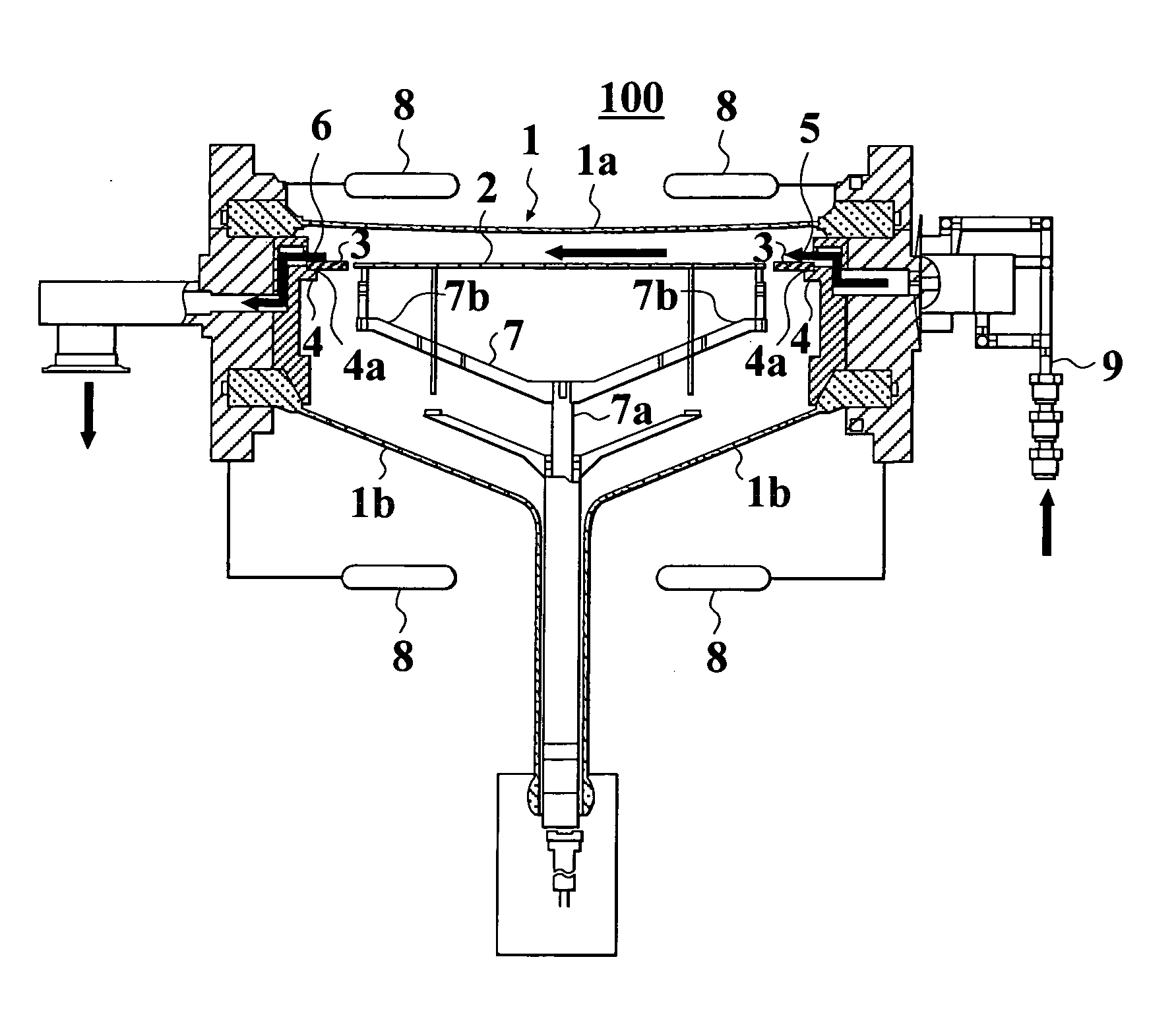
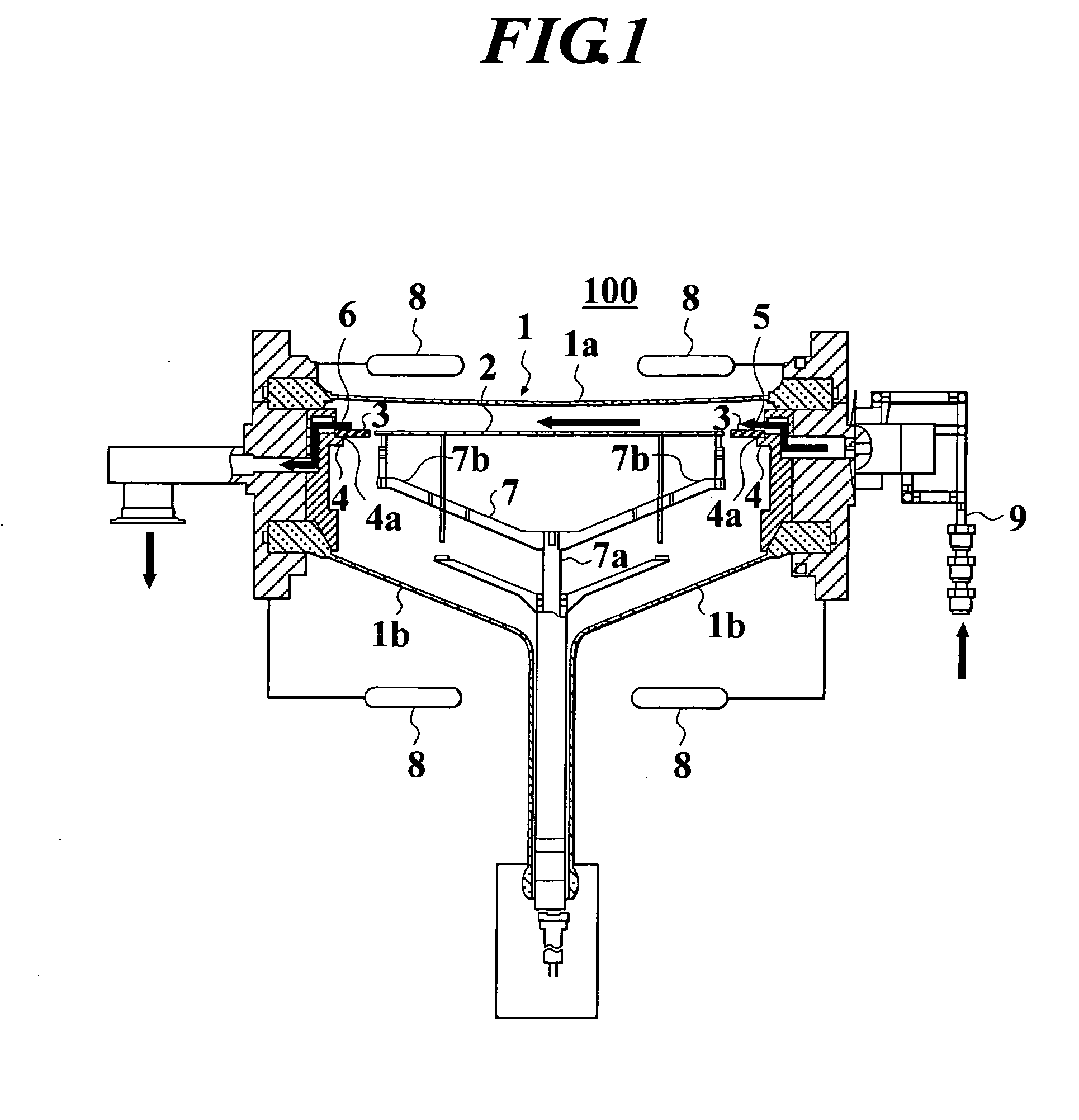
[0058] In this embodiment, vapor phase epitaxial growth was performed to a wafer of 300 mm in diameter by using the heat treatment apparatus 100 in FIG. 1.

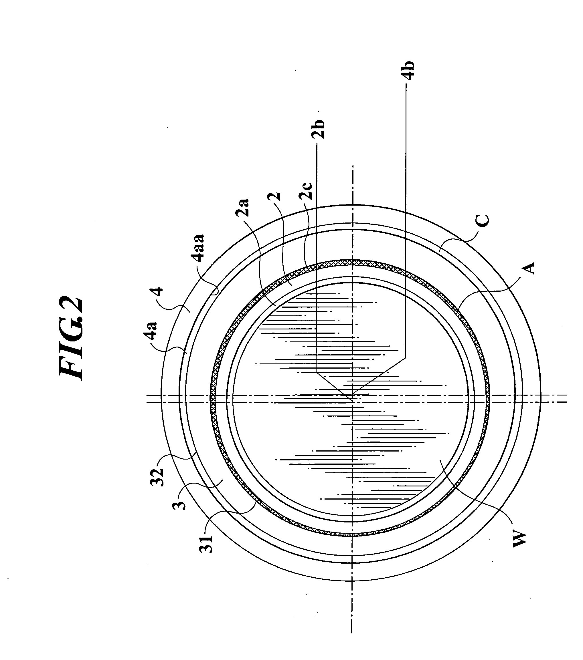
[0059] The heat treatment apparatus 100 used was such that the diameter of the outer periphery of the susceptor is about 373 mm, the diameter of the pocket inner periphery of the base is about 447 mm, and the center of the susceptor is misaligned by about 1 mm to the inner peripheral center of the base. The preheat ring was formed such that the inner diameter is about 377 mm, the outer diameter is about 443 mm, and the inner peripheral center is eccentric to the outer periphery to make the inner peripheral center be misaligned by 1 mm to the outer peripheral center.

[0060] According to the above described embodiment, after placing the preheat ring onto the pocket of the base, the preheat ring was positioned with respect to the pocket inner periphery of the base and the susceptor. In this state, there was a clearance ranging from ...


PUM

PropertyMeasurementUnit
Diameteraaaaaaaaaa
Sizeaaaaaaaaaa
Distanceaaaaaaaaaa

Abstract

A heat treatment apparatus (100) having: a susceptor (2) rotatably provided in a heat treatment vessel (1), on which a wafer (W) is placed; a preheat ring (3) surrounding a periphery of the susceptor (2) to be close to and in non-contact with the susceptor, which is supported by a base (4) provided in the heat treatment vessel (1); and a heating apparatus (8) for heating a wafer (W) placed on the susceptor (2), wherein the preheat ring (3) is formed such that an inner peripheral center (31a) is eccentric to an outer periphery (32). The preheat ring (3) is moved around the susceptor (2); the preheat ring (3) is positioned to minimize a distance between the inner peripheral center (31a) of the preheat ring (3) and the center (2b) of the susceptor (2); and thereafter a heat treatment is performed to a wafer (W).

Description

FIELD OF THE INVENTION [0001] This invention relates to a heat treatment apparatus and a heat treatment method for performing a heat treatment to a substrate. BACKGROUND ART [0002] Recently, a heat treatment apparatus has been used for processes such as forming a thin film, e.g., a silicon epitaxial layer, a silicon nitride film or the like on a front surface of a semiconductor substrate such as a silicon single crystal wafer (hereinafter, referred as wafer) or the like, performing etching thereto or the like. [0003] The heat treatment apparatus comprises, for example, a translucent heat treatment vessel made from quartz or the like, and a susceptor is provided inside thereof for placing and rotating a wafer. A heating apparatus comprising a halogen lamp or the like is provided around the heat treatment vessel so that a wafer placed on the susceptor can be heated from the outside of the heat treatment vessel. Further, a gas supply opening for supplying reaction gas or the like into ...

Claims


Application Information

Patent Timeline
IPC IPC(8): H01L21/00C23C16/458H01L21/205H01L21/687
CPCH01L21/67103H01L21/68735H01L21/67115H01L21/67109H01L21/324H01L21/68
Inventor OSE, HIROKI
Owner SHIN-ETSU HANDOTAI CO LTD
Why Eureka
Try Eureka