
Bone-adaptive surface structure

a surface structure and bone technology, applied in bone implants, medical science, dentistry, etc., can solve the problems of polymetallosis, inability to apply macromechanical surface structures to lateral implants, and inability to reduce costs, so as to improve the in-growth rate, improve the initial strength, and be easily inserted

Inactive Publication Date: 2005-05-19
BIOMED EST
View PDF13 Cites 10 Cited by
  • Summary
  • Abstract
  • Description
  • Claims
  • Application Information

AI Technical Summary

Benefits of technology

[0013] The advantageous effects noted above also appear if the surface structure consists of bowl-like depressions. The surface structures can be formed by variously shaped depressions and milled-out regions worked into the marginal zones of the base. In this variant embodiment, the geometry of the depressions, which differ from each other, should advantageously be selected such that the forms of the depressions in contact produce a configuration with reentrant angles. Furthermore, the substrate can in turn be formed so that it ends in the peripheral region of the base with a core height of h2.
[0014] Aside from the advantages noted which are also attainable with this solution, the peripheral depressions in the base substantially improve the in-growth because the jaw bones tend to close, reaching and filling out the depressions with smaller configurations sooner than those with somewhat larger configurations. In this way, a high initial strength can be attained considerably sooner.
[0015] If lateral implants also have elastic properties, then the threaded parts sink into the spongy bones under stress. That results in a tension directed centrally on the threaded parts. In this situation, the surfaces of the previously known lateral implants can tear out of the bone combination. However, due to the surface structures according to the invention, it is possible to maintain the combination with the bone even under large stresses. Thus individual implants can be more heavily loaded, with the result that fewer implants per jaw are needed to reproduce the ability to chew. In this way, even severely atrophied jaws can be cared for without bone grafting.
[0016] With proper selection of microdimensions and macrodimensions, it is possible to provide an implant which fits biomechanically into the bone but is still easily insertable, and which has a surface structure that offers the implant optimal macromechanical hold in the jawbone. Then the vertically acting masticatory forces are absorbed in an astonishing manner by the likewise vertical structures such as, for example, the grooves made in the surface of the implant base and / or bar.
[0017] It is also possible to elevate the surface structure by sintering one or more layers of balls of titanium or a titanium alloy having a diameter of 120 to 220 μm onto the desired surfaces of the implant. This likewise provides higher surface roughness without additional micromechanical measures such as those described above.
[0018] From extensive series of histological examinations and cracking tests, it has been found that the best results for adhesion are attained with the dimensions shown below for the bases and surface structures:

Problems solved by technology

At first glance, it appears impossible to apply macromechanical surface structures to lateral implants.
Dispensing with such measures not only reduces cost, but also prevents the layers applied from producing supplemental microstructure separating from the surface during insertion of the implant, or later, thus causing inflammation and symptoms resembling polymetallosis.

Method used


Image

  • Bone-adaptive surface structure
  • Bone-adaptive surface structure
  • Bone-adaptive surface structure

Examples


Embodiment Construction

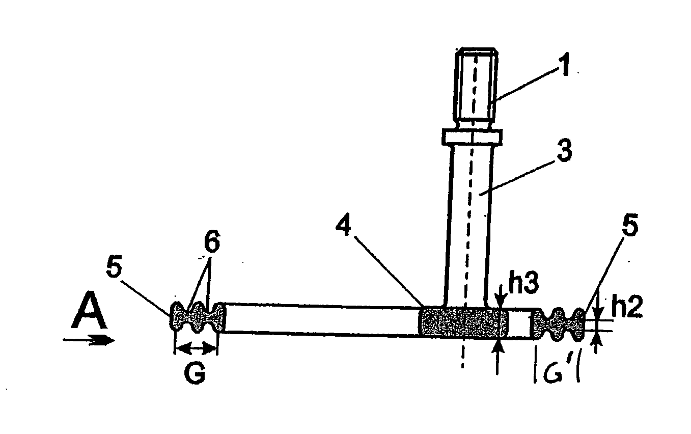
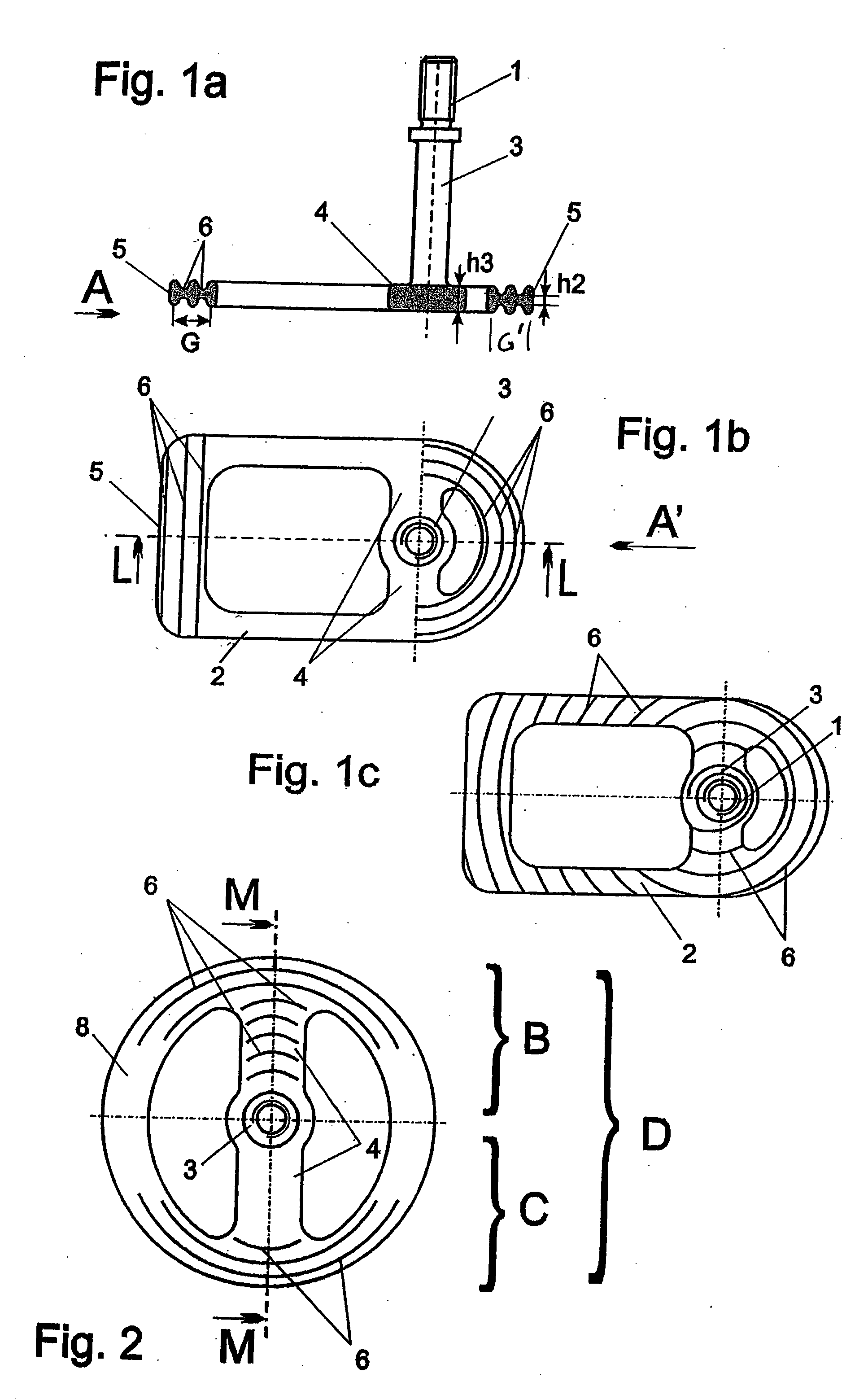
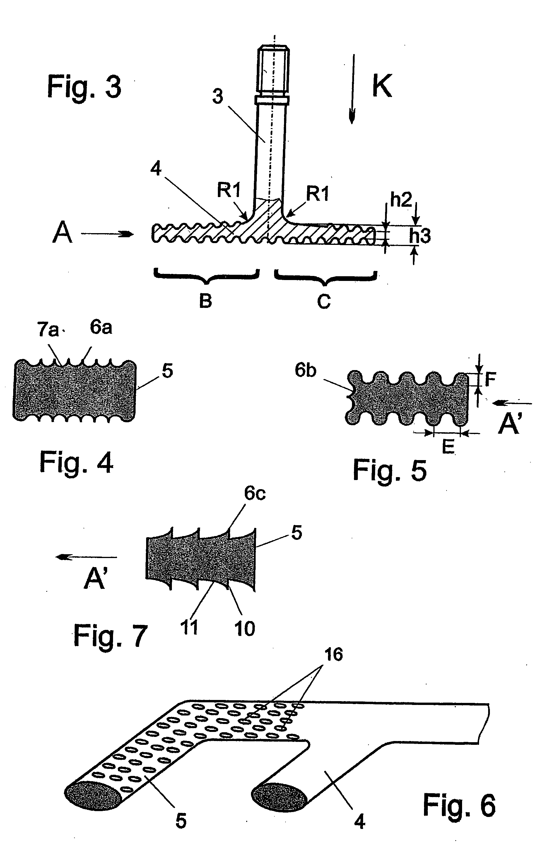
[0048] As can be seen in FIG. 1a, a screw thread 1 is provided at a distal end of a shaft 3 for connecting with a prosthesis (not shown). The thread can be an internal or external thread. In appropriate circumstances the prosthesis can be adhesively secured, as by an epoxy. FIG. 1b shows a base 2 in the form of an annular body of a lateral dental implant. A bar 4 connects the shaft 3 to the base 2. It has been determined that implants of this type transfer the masticatory force essentially into the peripheral annular section of the base 2, indicated here by 5, which is anchored in the cortical jaw bone. As shown in FIGS. 4, 5 and 7, numerals 6a, 6b and 6c indicate various surface structures embodying the invention that may be on the base 2. In FIG. 1a, the letter G indicates the width of an outer ring of the base 2 or of a base 8 (see FIG. 2).

[0049] In the embodiment shown in FIG. 1b, the surface structures are formed by periodic grooves 6 which can run parallel with each other, as...


PUM


Abstract

Bone-adaptive surface structures are provided for lateral jaw implants. Micromechanical and / or macromechanical surface structures having various body forms are incorporated into selected segments of the surface of a base and of a bar that connects a shaft with the base to accelerate the healing process after the implant is inserted into the jaw bone and to make a critical improvement in holding the implant firmly in place without rotation. A process of manufacturing the surface structures includes forming a macromechanical surface on the implant to increase its surface area; and superimposing micromechanical canals on the macromechanical surface, the canals having a size smaller than the minimum size of the osteons in the bone into which the implant is to be inserted.

Description

CROSS REFERENCE TO RELATED APPLICATIONS [0001] This application is a continuation-in-part of pending U.S. application Ser. No. 10 / 714,200 filed Nov. 14, 2003, and claims priority of EP 02090379.5 filed Nov. 15, 2002, which claims priority to DE 20208975 U filed Jun. 10, 2002.TECHNICAL FIELD OF THE INVENTION [0002] The invention concerns bone-adaptive surface structures for orthopedic implants, particularly lateral jaw implants (basal osseointegration); that is, for implants which are inserted into the jaw from the side, and which are also known as “disk implants.”DESCRIPTION OF THE RELATED ART [0003] Various industrially produced implants have been used for decades in dental implantology. These include cylinder implants, screw implants, leaf implants, and disk implants. Individually produced subperiostal implants also play a part. [0004] These implants developed from a kind of box shape. They generally have a disk-shaped implant base. U.S. Pat. No. 3,925,892 (Juillet) describes an i...

Claims


Application Information

Patent Timeline
IPC IPC(8): A61C8/00
CPCA61C8/0018A61C8/001
Inventor IHDE, STEFAN
Owner BIOMED EST
Learn More