Motorized roller

a motorized roller and roller technology, applied in the direction of conveyor parts, mechanical energy handling, transportation and packaging, etc., can solve the problems of restricted temperature range, difficult to solve conventional problems, restricted motor power and continuous operation time, etc., to achieve compact size, high reliability, and simple coil structure

Active Publication Date: 2005-05-26
SUMITOMO HEAVY IND LTD
View PDF6 Cites 17 Cited by
  • Summary
  • Abstract
  • Description
  • Claims
  • Application Information

AI Technical Summary

Benefits of technology

[0017] Since the resolver has a simple coil structure, and does not have an electronic circuit, the resolver is compact in size, and is available in a wide temperature range with high reliability. Accordingly, the combination of the brushless DC motor and the resolver can maximize the advantages of the brushless DC motor. Namely, the brushless DC motor is available in the wide temperature range with high reliability, in addition to being compact in size and low cost. Also, it is possible to obtain the motorized roller which can continuously operate in a high power region, in which the diameter of the roller is 125 mm or less and the capacity of the motor is 0.1 kw or more, though the continuous operation in the high power region have been conventionally considered to be impossible.
[0018] Various exemplary embodiments of the present invention can provide compact motorized rollers at low cost. The motorized roller is usable in the wide temperature range with high reliability, and can continuously operate with high power.

Problems solved by technology

The Hall integrated circuit, however, is sensitive to heat, and hence an available temperature range is confined.
Thus, it is difficult to solve the conventional problems that motor power and continuous operation time are restrained.
Furthermore, there is a limit to precisely detecting a turning angle by the Hall integrated circuit, so that the Hall integrated circuit is not suited for feedback control with high precision.

Method used


Image

  • Motorized roller
  • Motorized roller
  • Motorized roller

Examples


Embodiment Construction

[0027] Various exemplary embodiments of this invention will be hereinafter described in detail with reference to the drawings.

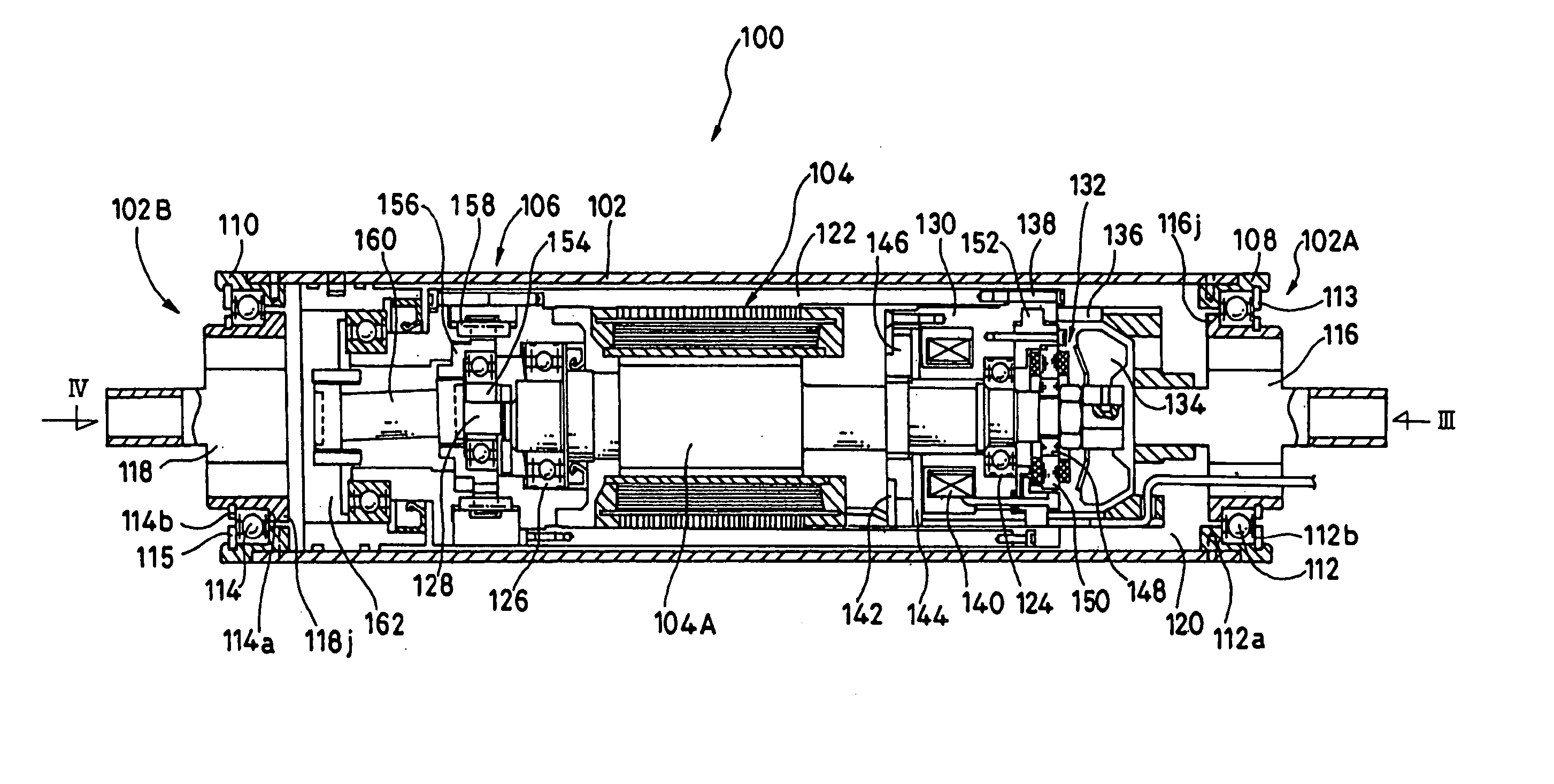
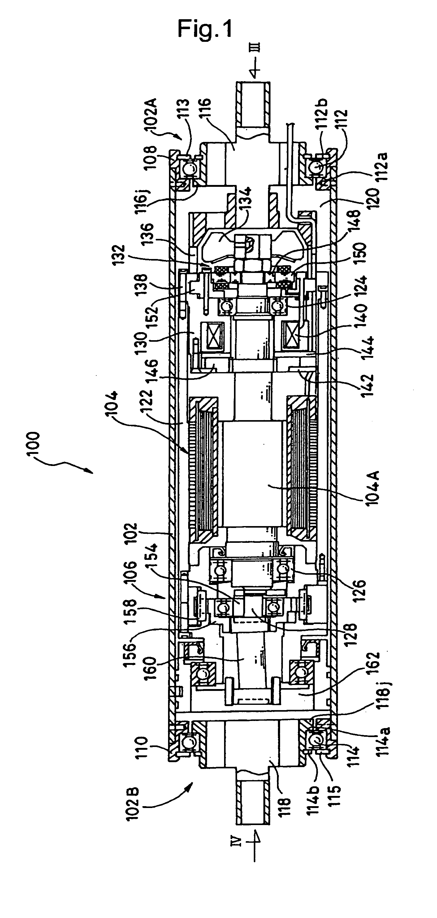
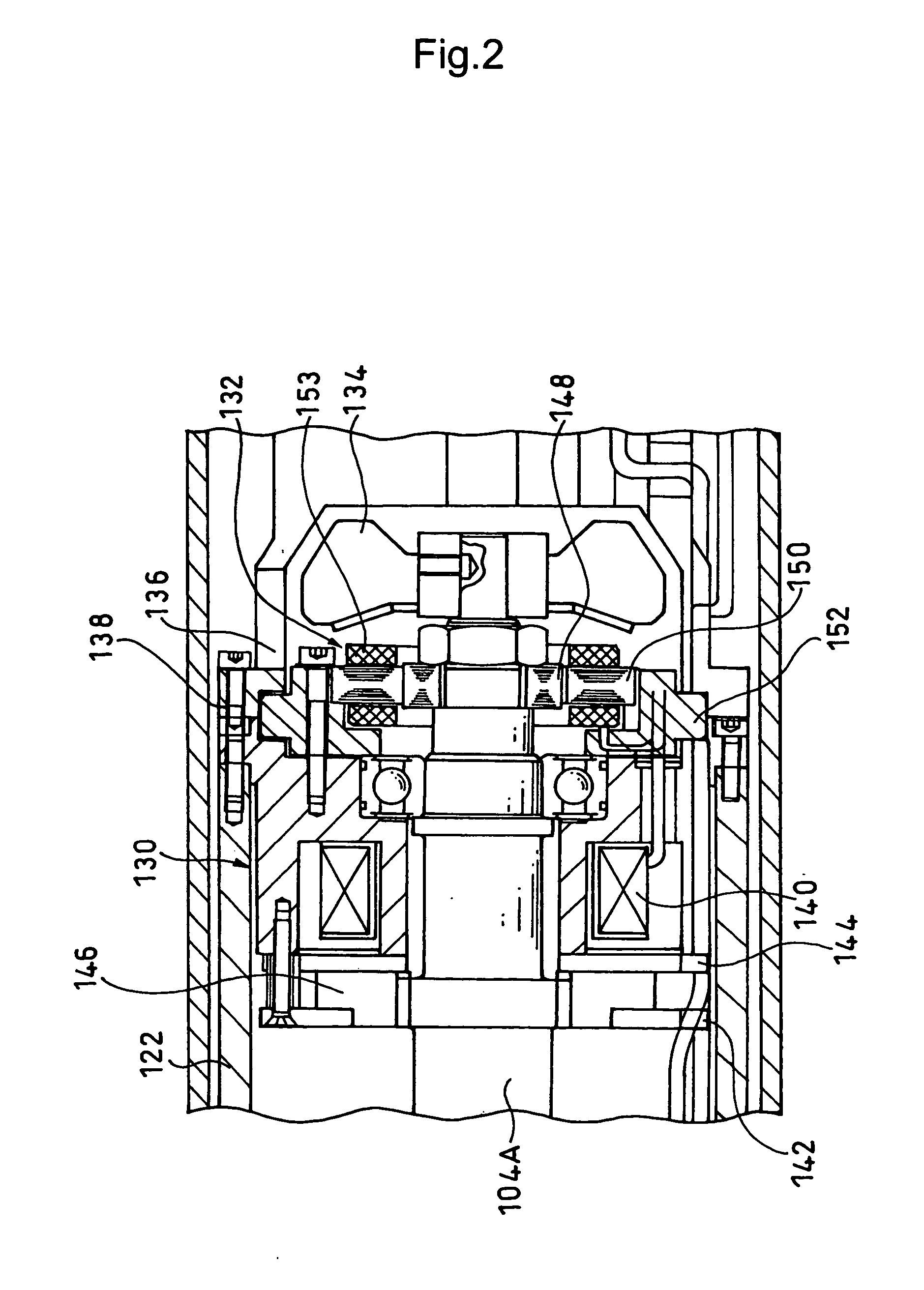
[0028]FIGS. 1 and 2 show a motorized roller 100 according to an embodiment of the present invention. FIG. 1 is a side sectional view of the motorized roller 100 corresponding to the one shown in FIG. 6, and FIG. 2 is an essential enlarged sectional view of FIG. 1. FIGS. 3 and 4 are sectional views viewed from directions of the arrows III and IV in FIG. 1, respectively.

[0029] A roller body 102 of the motorized roller 100 is composed of a substantially cylindrical member. A motor 104 and a reducer 106 are contained in the internal space of the roller body 102. Bearings 112 and 114 are disposed at both ends 102A and 102B of the roller body 102 with ring-shaped members 108 and 110 interposed therebetween, respectively. A pair of first and second attachment brackets 116 and 118 are rotatably supported with respect to the roller body 102 with the bearings 112 and...


PUM


Abstract

A compact motorized roller, which is usable in a wide temperature range with high reliability and is manufactured at low cost. The motorized roller has a motor in a roller body. The motor can rotate the roller body. In such a motorized roller, the motor is a brushless DC motor, and a resolver is installed as a magnetic pole position detector of the brushless DC motor.

Description

BACKGROUND OF THE INVENTION [0001] 1. Field of the Invention [0002] The present invention relates to a motorized roller such as a motor pulley and a motor roller used in a conveyor or the like. [0003] 2. Description of the Related Art [0004] Various motorized rollers have been conventionally proposed. Such a roller has a roller body and a motor contained in the roller body, and the motor rotates the roller body. This type of motorized roller is, as shown in FIG. 5 for example, used as a motor roller MR, which is disposed on a conveyor 2 to directly convey a package 4. Otherwise, the motorized roller, as shown in FIG. 6, may be used as a motor pulley MP for conveying a package 4 with the use of a belt 6. [0005]FIG. 7 schematically shows a side sectional view of a conventionally known motorized roller 10 (refer to, for example, Japanese Patent Laid-Open Publication No. 1994-227630). [0006] This motorized roller 10 comprises a roller body 11 of a substantially cylindrical member, a mot...

Claims


Application Information

Patent Timeline
Patent Type & Authority Applications(United States)
IPC IPC(8): B65G13/06B65G13/02B65G23/08B65G39/10H02K7/10H02K7/102H02K7/116H02K9/06H02K11/00H02K29/06
CPCB65G23/08H02K7/1012H02K11/00H02K9/06H02K7/1025
Inventor HAYASHI, HIDETOSHIUMEDA, KAZUYOSHI
Owner SUMITOMO HEAVY IND LTD
Why Eureka
Try Eureka