
Electronic heat pump device, laser component, optical pickup and electronic equipment

a heat pump device and laser technology, applied in the direction of semiconductor/solid-state device details, lighting and heating apparatus, optical beam sources, etc., can solve the problems of reducing life, fluctuation in wavelengths, and affecting the efficiency of heat pump devices, so as to reduce the amount of power consumption

Inactive Publication Date: 2005-05-26
SHARP KK
View PDF13 Cites 20 Cited by
  • Summary
  • Abstract
  • Description
  • Claims
  • Application Information

AI Technical Summary

Benefits of technology

The present invention provides a subminiature electronic heat pump device that is designed to secure a vacuum gap without using piezo devices and has a reduced power consumption. The device includes an emitter and a collector with vacuum gaps between them, and a spacer section that keeps the space constant and electrically and thermally insulative. A sealing member is used to maintain the vacuum state. The device can be installed in a package of a semiconductor laser component, making it ideal for use in a hologram laser system. The invention reduces the number of component parts, size, weight, and cost of the electronic heat pump device.

Problems solved by technology

The semiconductor laser diode device emits light while generating heat whose energy is several times larger than that of the light, and therefore it is concerned that the heat generated by the semiconductor laser diode itself might cause fluctuation in wavelengths and decrease in life.
However, the first to third prior art examples had following problems.
However, inside the p-type semiconductor 106 and the n-type semiconductor 107, there is heat current due to thermal conduction as shown by an arrow 122, which causes a problem of low cooling efficiency and large power consumption.
However, in this second prior art example, in order to maintain the vacuum gap 113 of 10 nm or less, the piezo device 114 shown in FIG. 19 as well as an electrostatic capacity controller 117 for feedback control of the vacuum gap 113 are required, which causes a problem that the apparatus becomes big and thereby reduction in size and weight is hindered.
However, as shown in FIG. 20, heat flows through the barrier 119 interposed in between the emitter electrode 111 and the collector electrode 112 due to thermal conduction, which causes a serious problem of poor cooling efficiency and large power consumption because of the same reason as the peltiert device.

Method used


Image

  • Electronic heat pump device, laser component, optical pickup and electronic equipment
  • Electronic heat pump device, laser component, optical pickup and electronic equipment
  • Electronic heat pump device, laser component, optical pickup and electronic equipment

Examples


first embodiment

The First Embodiment

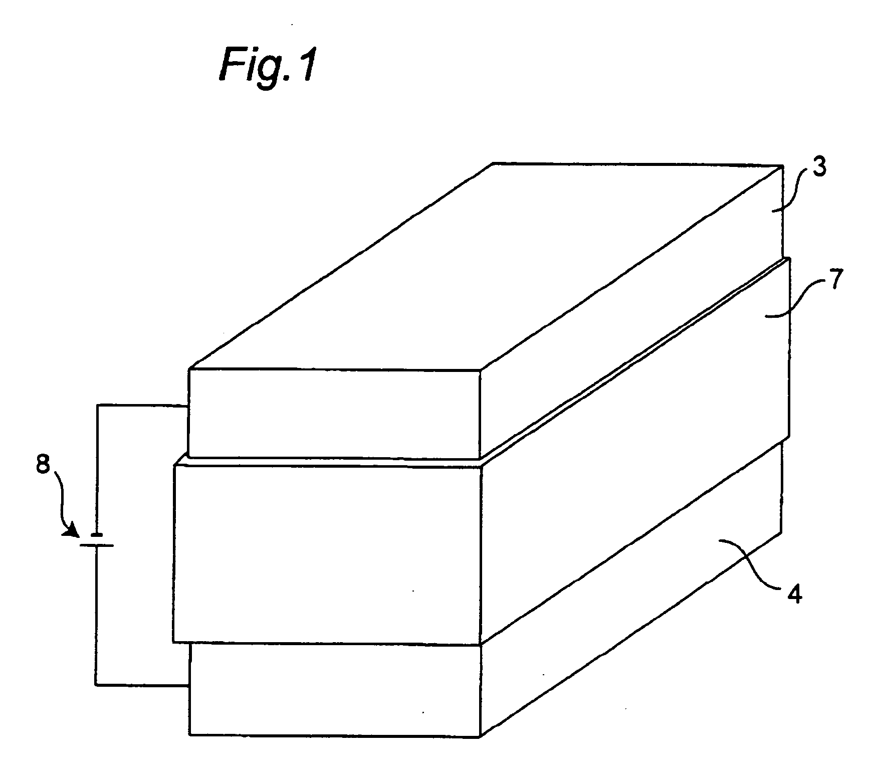
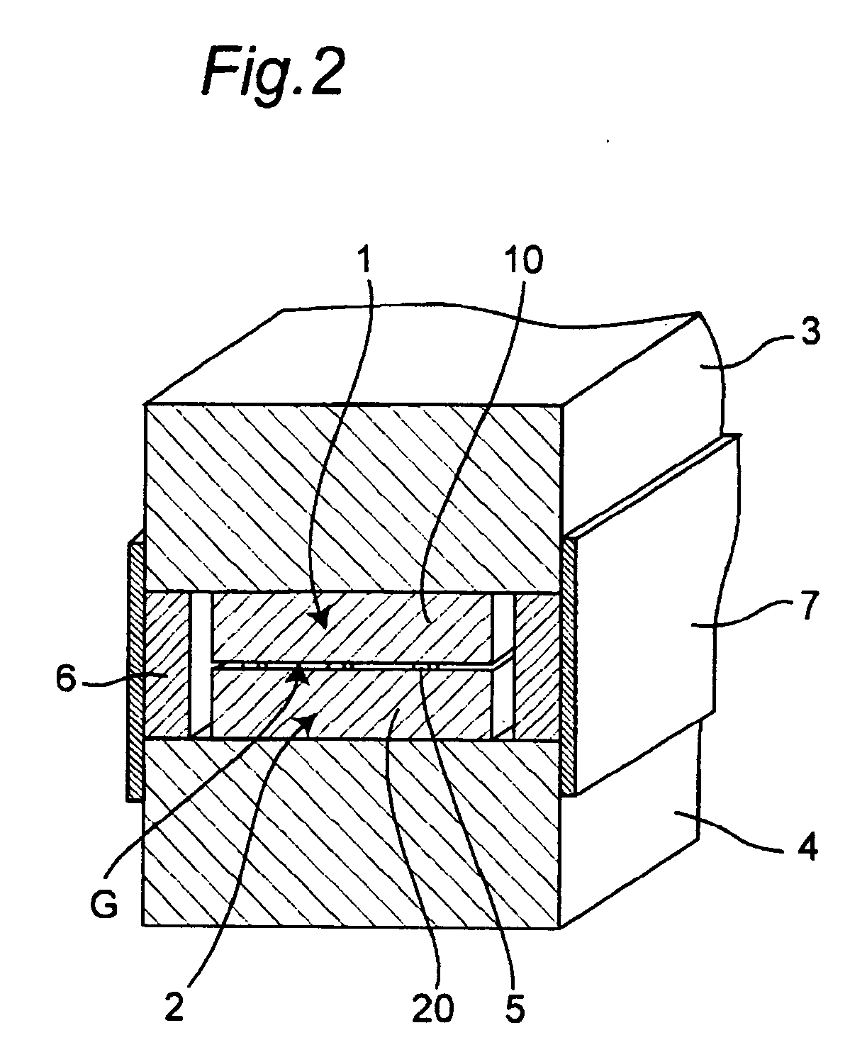
[0132]FIG. 1 is a perspective view showing an electronic heat pump device in one embodiment of the present invention, and FIG. 2 is a sectional view showing the electronic heat pump device.

[0133] The electronic heat pump device includes an emitter-side external electrode substrate 3 having electric and thermal conductivity and having an almost rectangular parallelepiped shape, an emitter 1 which is connected to the emitter-side external electrode substrate 3 so as to allow conduction of electricity and heat and which emits electrons, a collector-side external electrode substrate 4 having electric and thermal conductivity and having an almost rectangular parallelepiped shape, a collector 2 which is connected to the collector-side external electrode substrate 4 so as to allow conduction of electricity and heat and which receives electrons, an electrically and thermally insulative space retention member 6 which is disposed between the emitter-side external electrod...

second embodiment

The Second Embodiment

[0190] Next, a laser component of the present invention, as shown in the perspective view of FIG. 16 and the main portion enlarged view of FIG. 17, includes a package 56, the electronic heat pump device 51 installed in the package is 56, a semiconductor laser diode chip 52 (hereinbelow referred to as an LD chip) mounted on the emitter-side external electrode substrate 3 of the electronic heat pump device 51, a temperature detector 61 for detecting the temperature of the LD chip 52, an electric power controller 62 for controlling electric power supplied to the electronic heat pump device 51 so as to keep the LD chip 52 at a predetermined temperature based on the temperature detected by the temperature detector 61.

[0191] Moreover, the laser component is a hologram laser component which includes a light-receiving element 54 mounted on a stem 53 inside the package 56 and a hologram device 55 attached to the external portion of the package 56, and which emits a lase...

third embodiment

The Third Embodiment

[0202] Next, though unshown, an optical pickup of the present invention includes the laser component. According to the optical pickup, the laser component is provided, which makes it possible to achieve the optical pickup which ensures a stable temperature of the LD chip and which is resistant to change in operating environment temperature without modification in exoergic design or modification in mounting space.


PUM

PropertyMeasurementUnit
sizeaaaaaaaaaa
thicknessaaaaaaaaaa
thermal conductivityaaaaaaaaaa

Abstract

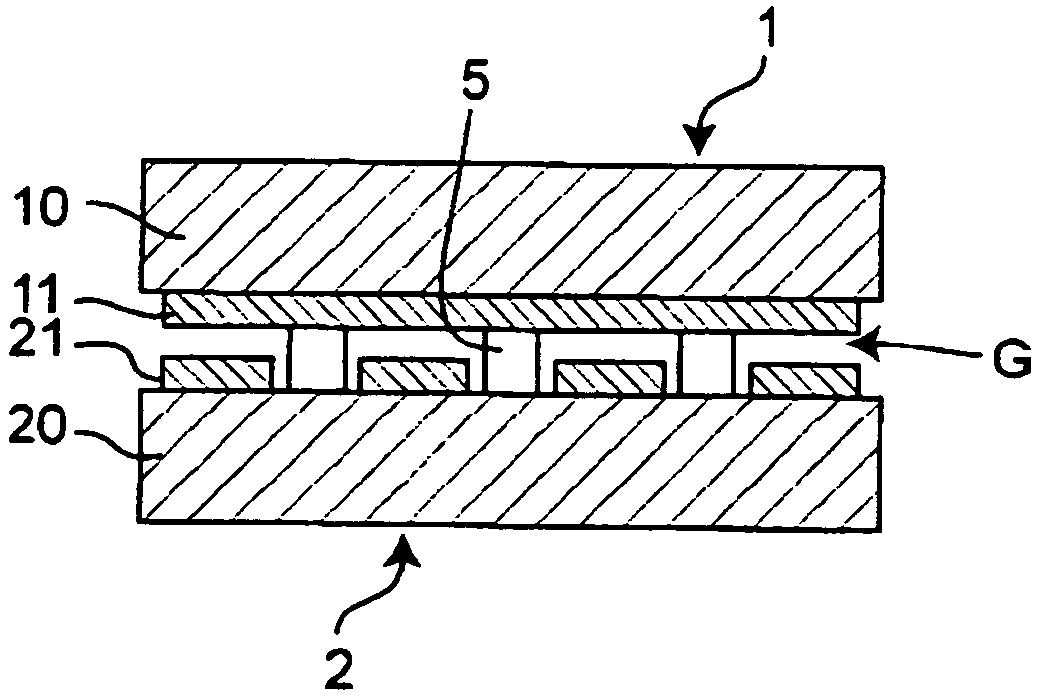
There is provided a small-size electronic heat pump device which is low in power consumption and which secures a vacuum gap without use of an additional circuit. The electronic heat pump device includes an emitter 1 and a collector 2. An electrically and thermally insulative spacer section 5 for keeping a space, i.e. vacuum gap G between an emitter electrode 11 and a collector electrode 21 constant is integrally formed in a semiconductor substrate 20 of the collector 2, which makes it possible to maintain the vacuum gap to be a specified space while a back flow of heat is prevented in a simple structure with a reduced number of component parts.

Description

CROSS-REFERENCE TO RELATED APPLICATION [0001] This nonprovisional application claims priority under 35 U.S.C. §119(a) on Patent Application No. 2003-393448 filed in Japan on Nov. 25, 2003, the entire contents of which are hereby incorporated by reference. BACKGROUND OF THE INVENTION [0002] The present invention relates to an electronic heat pump device for transporting heat from a low temperature section to a high temperature section through, for example, application of a current. The present invention also relates to a laser component for cooling a semiconductor laser diode device by using the electronic heat pump device, an optical pickup equipped with the laser component, and electronic equipment equipped with the electronic heat pump device. [0003] In recent years, images and data recorded by writable optical disk apparatuses are rapidly expanding, by which recording rates as well as optical output from the writable semiconductor laser diodes are steadily increasing. [0004] The ...

Claims


Application Information

Patent Timeline
Patent Type & Authority Applications(United States)
IPC IPC(8): F25B21/00G11B7/125G11B7/126H01L23/38H01L29/76H01S5/022H01S5/024H01S5/068H02N3/00H10N15/00
CPCF25B21/00F25B2321/003G11B7/126H01L23/38H01L37/00H01S5/02208H01S5/02407H01L2924/0002H01S5/02415H01S5/06808Y02B30/66Y10S257/93H01L2924/00Y02B30/00H10N15/00
Inventor SHIMOGISHI, KENJIMATSUO, YOSHIHIKOTSUDA, YOICHI
Owner SHARP KK
Learn More