Software GPS based integrated navigation

a software gps and integrated navigation technology, applied in vehicle position/course/altitude control, process and machine control, instruments, etc., can solve the problems of mixing circuit design and re-design, and high cost of gps receiver design and developmen

Inactive Publication Date: 2005-05-26
HONEYWELL INT INC
View PDF8 Cites 11 Cited by
  • Summary
  • Abstract
  • Description
  • Claims
  • Application Information

AI Technical Summary

Benefits of technology

[0013] According to one aspect of the present invention, a method performed by a GPS receiver of processing GPS data comprises the following: acquiring GPS data from at least one GPS satellite, wherein the GPS data is useful in determining GPS position of the GPS receiver; performing acquisition functions in the frequency domain based on the GPS data, wherein the acquisition functions produce acquisition results, and wherein the performing of the acquisition functions cause a delay in handing over the acquisition results to a tracking function; propagating the acquisition results forward in time by an amount of time substantially equal to the delay; and, handing over the propagated acquisition results to the tracking function.

Problems solved by technology

The design and development of this mixing and band pass filter hardware is an expensive part of the GPS receiver.
Not only does this mixing and band pass filter hardware add recurring cost, but mixing circuit designs and re-designs add non-recurring cost whenever even a small change is made to the frequency characteristics of the system.
Furthermore, this frequency-specific hardware also typically suffers from changes as a result of aging.
However, implementation of a such software based GPS receiver is challenging.
One particular challenge encountered in designing a software based GPS receiver is in performing the handover between frequency domain acquisition and time domain tracking.
This challenge arises because, if software based GPS position acquisition is done in the frequency domain with a “batch” of data, acquisition can take a non-trivial amount of time and, thus, there is a time gap between when the data used for acquisition is collected and when the acquisition solution is actually computed.
Moreover, implementing signal acquisition in the frequency domain may be desirable for reasons other than reducing hardware, in which case the time required to hand over processing from acquisition to tracking is still a problem.

Method used


Image

  • Software GPS based integrated navigation
  • Software GPS based integrated navigation
  • Software GPS based integrated navigation

Examples


Embodiment Construction

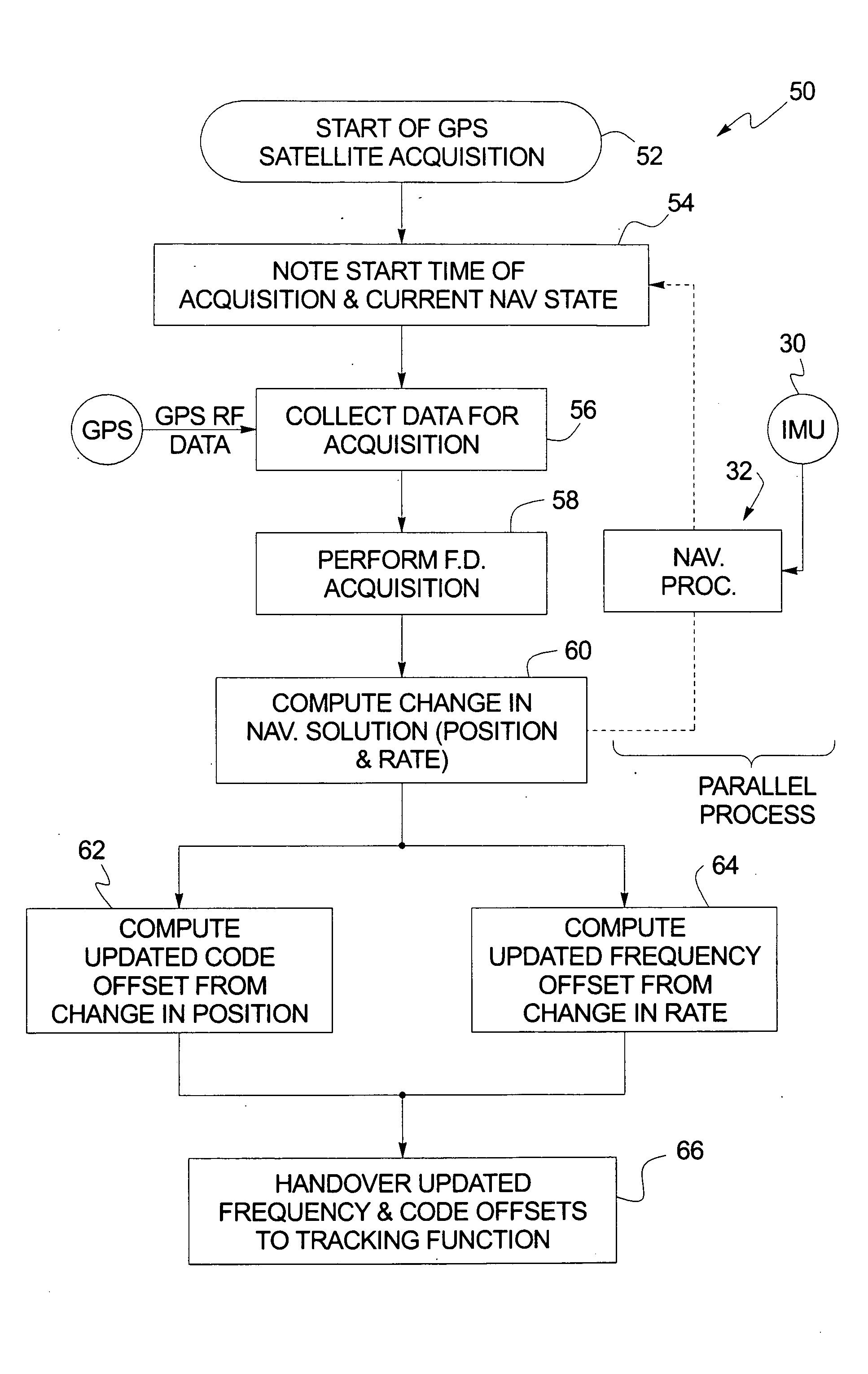
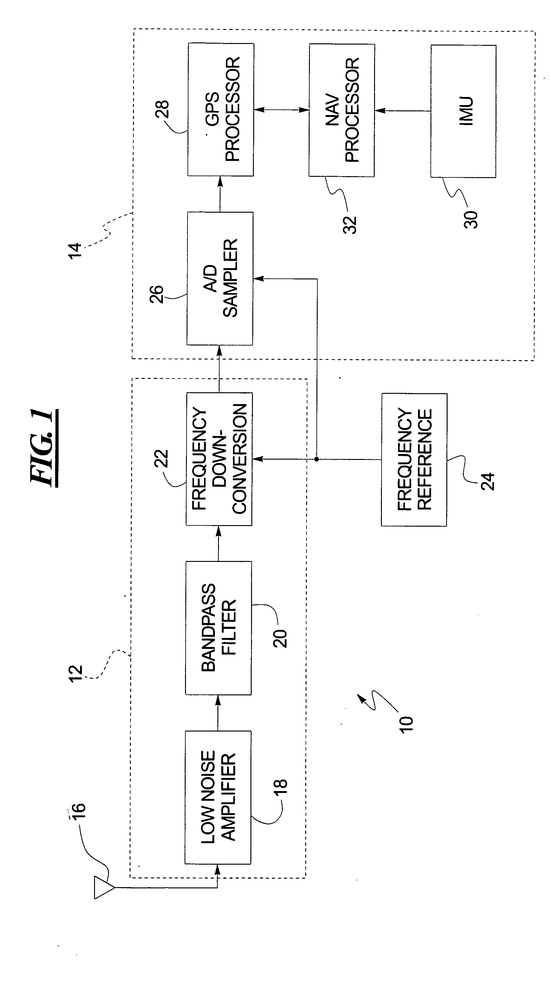
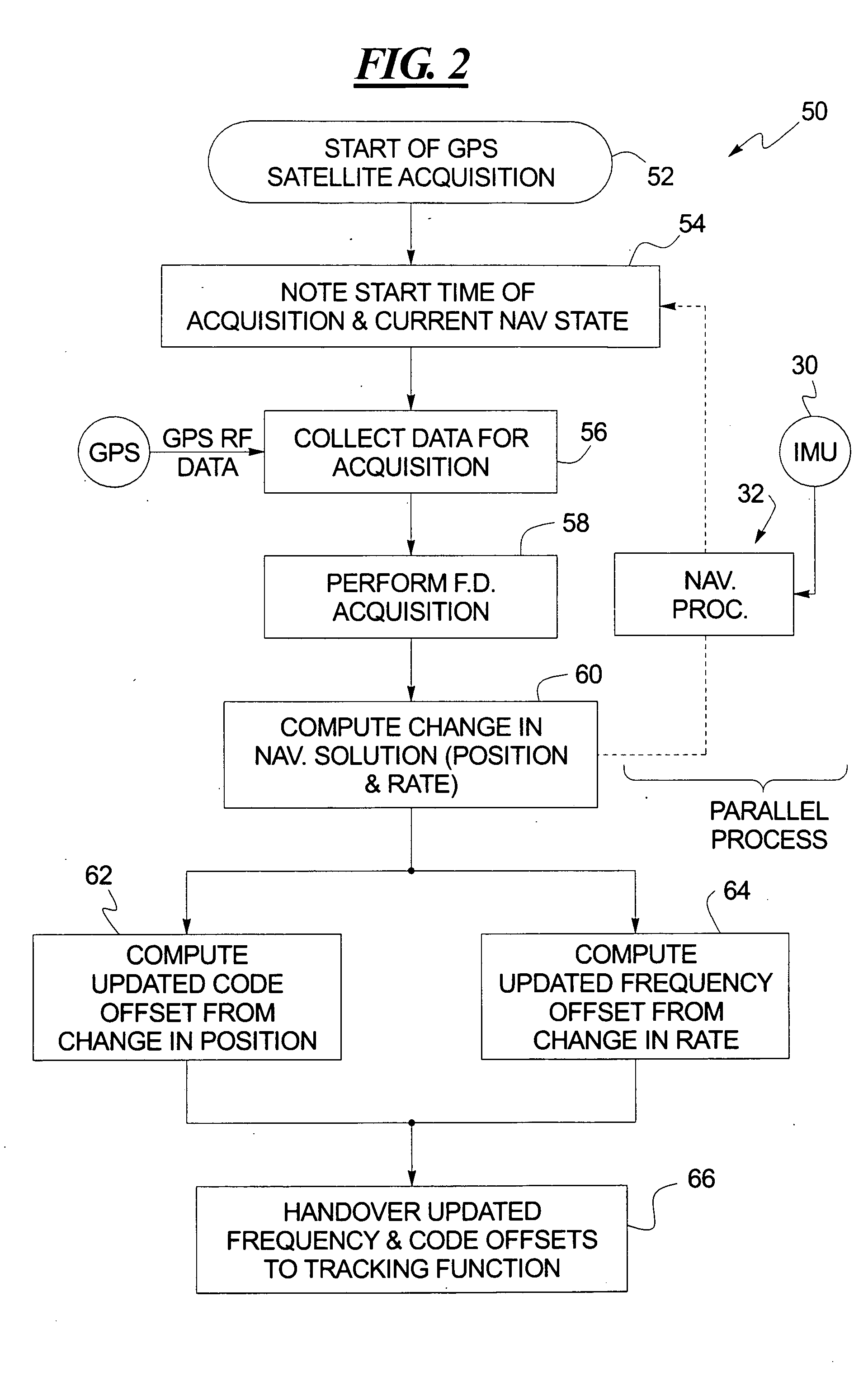
[0019] As shown in FIG. 1, a GPS receiver 10 includes a GPS front end 12 and a system processor 14. The GPS front end 12 receives the incoming analog GPS signal from a GPS antenna 16. This analog GPS signal is amplified by a low noise amplifier 18 and is filtered by a bandpass filter 20. The low noise amplifier 18 and the bandpass filter 20 may be provided in multiple stages, if desired.

[0020] The analog GPS signal at the output of the bandpass filter 20 is downconverted in a frequency downconverter 22 by mixing the analog GPS signal with a local oscillator signal to shift the carrier frequency of the incoming analog GPS signal to a lower and more manageable frequency band. This downconversion can be performed multiple times to bring the frequency of the analog GPS signal down in steps to the final desired frequency. Each mixing operation produces a high frequency information band along with the lower frequency band. Therefore, each mixing stage of the frequency downconverter 22 ma...


PUM


Abstract

A GPS receiver acquires GPS data from at least one GPS satellite. A code offset and a frequency offset are determined based on the acquired GPS data. A change in GPS position of the GPS receiver during the determination of the code offset is determined, and a change in rate of the GPS receiver during the determination of the frequency offset is also determined. The code offset is updated based on the change in GPS position, and the frequency offset is updated based on the change in rate. The updated code offset and the updated frequency offset are handed over to a tracking function.

Description

TECHNICAL FIELD OF THE INVENTION [0001] The present invention relates to signal acquisition and tracking in a GPS system. BACKGROUND OF THE INVENTION [0002] The Global Positioning System (GPS) is a satellite-based navigation system developed and operated by the U.S. Department of Defense. GPS permits land, sea, and airborne users to determine their three-dimensional positions, velocities, and time. [0003] GPS uses NAVSTAR (NAVigation Satellite Timing and Ranging) satellites. The current constellation consists of 21 operational satellites and 3 active spares. This constellation provides a GPS receiver with four to twelve useable satellites from which it can receive GPS satellite signals at any time. A minimum of four satellites allows the GPS receiver to compute its GPS position (latitude, longitude, and altitude) and GPS system time. Altitude is typically referenced to mean sea level. [0004] The GPS satellite signal from the NAVSTAR GPS satellites contains information used to identi...

Claims


Application Information

Patent Timeline
Patent Type & Authority Applications(United States)
IPC IPC(8): G01S19/29G01S1/00G01S5/14G01S19/30G05D1/00G05D1/08
CPCG01S19/26G01S19/37G01S19/30G01S19/29
Inventor SCHIPPER, BRIAN W.BYE, CHARLES T.
Owner HONEYWELL INT INC
Why Eureka
Try Eureka