Pedestrian navigation system and method

a technology for pedestrian navigation and navigation solutions, applied in navigation instruments, distance measurement, instruments, etc., can solve problems such as inability to guarantee the occurrence of such a condition, inability to provide exterior indications or signals, and errors accumulated, so as to reduce the accumulation of inertial drift errors and increase the accuracy of said corrected navigation solutions.

Active Publication Date: 2013-01-15
ISRAEL AEROSPACE IND
View PDF26 Cites 9 Cited by
  • Summary
  • Abstract
  • Description
  • Claims
  • Application Information

AI Technical Summary

Benefits of technology

[0012]According to another embodiment of the invention there is provided a sensor arrangement useful for pedestrian navigation, the sensor arrangement comprising a first navigation module and a second navigation module, each navigation module comprising: at least a first sensor unit and a second sensor unit, wherein each sensor unit including an up / down sensor adapted for sensing an ‘up’ condition and a ‘down’ condition associated with relative displacement of the module with respect to a surface, and a signal transmitter / receiver adapted, in response to an activation signal coming from a module controller, for generating a propagating signal; a module controller for controlling the operation of the module in response to a control signal coming from the control unit; a communication unit for enabling said module to communicate with said at least the control unit and other module, wherein said control unit is adapted for: receiving from said first module and second module data indicative of a condition of respective up / down sensors; applying on said data a predetermined pedestrian motion model and in response, generating an activating signal for causing a selected acoustic transducer accommodated on the first or second module to generate an acoustic signal; and in case an acoustic transducer accommodated on the first module is activated, receiving from at least the second module data indicative of a receipt of said acoustic signal by at least two other acoustic transducers, and in case an acoustic transducer accommodated on the second module is activated, receiving said data from at least the first module; and repeating said operations (i)-(iii) during a pedestrian motion, thereby enabling TOA (Time of Arrival) processing which is useful in determining momentary positions of the pedestrian during motion.
[0018]wherein said pedestrian navigation further comprising a ZUPT checker coupled to said error corrector, navigation processing unit and control unit, wherein said ZUPT checker is adapted for checking if a predetermined ZUPT validity condition is met and: if to the affirmative, continuing applying said correction signal to said navigation signal; and if to the alternative, applying a DR signal to said navigation signal until said ZUPT validity condition is met again, thereby reducing accumulation of inertial drift errors and increasing accuracy of said corrected navigation solution.
[0019]According to an embodiment of the invention there is provided a navigation method useful for pedestrian navigation, comprising: (a) associating at least three touch points with heel area and toes area of said pedestrian's left foot and right foot; (b) collecting up / down information about a relative displacement of each of said touch points with respect to a surface; (c) based on said up / down information and in accordance with a predetermined pedestrian motion model and a predetermined transmission / receiving scheme, generating a propagating wave at least at one of said touch points; (d) collecting information of receipt of said propagating wave at least by part of said touch point, this information including Time-of-Arrival information, thereby enabling TOA (Time of Arrival) processing which is useful in determining DR (Dead-Reckoning) momentary positions of the pedestrian during motion.
[0025]According to yet another embodiment of the invention, there is provided a computerized method for reducing accumulation of inertial drift errors associated with an IMU (Inertial measuring Unit) in processing of a pedestrian navigation solution, the method comprising: (i) providing position value, velocity value and attitude value based on measurements carried out at least by said IMU; (ii) providing position correction, velocity correction and attitude correction calculated based on zero-velocity updates (ZUPT); (iii) generating a corrected position value, corrected velocity value and corrected attitude value by correcting said position value, velocity value and attitude value based on said position correction, velocity correction and attitude correction as long as a predetermined ZUPT validity condition is met, and in case said predetermined ZUPT validity condition is not met, correcting said position value, velocity value and attitude value based on at least a DR position correction calculated based on measurements provided by a Dead-Reckoning (DR) unit; (iv) using said corrected position value, corrected velocity value and corrected attitude value for processing said pedestrian navigation solution, and (v) repeating operations (i)-(iv) as many times as required.
[0035]thereby enabling TOA (Time of Arrival) processing which is useful in determining momentary positions of the pedestrian during motion.

Problems solved by technology

An IMU solution typically suffers from errors accumulated due to inertial sensor's drifts: even a small inertial measurement error contributes to high position error, which rapidly grows as a high order polynomial function of time.
However, a problem arises when such exterior indications or signals are unavailable or not exploitable, e.g. when a GPS signal is blocked or degraded, even occasionally, or when the LAN is unavailable.
However during certain motion types including forward short-step walking, occurrence of such a condition is not always guaranteed.
GETA sandals are typically provided with a wooden sole and this typically imposes a burden on the pedestrian.

Method used


Image

  • Pedestrian navigation system and method
  • Pedestrian navigation system and method
  • Pedestrian navigation system and method

Examples


Embodiment Construction

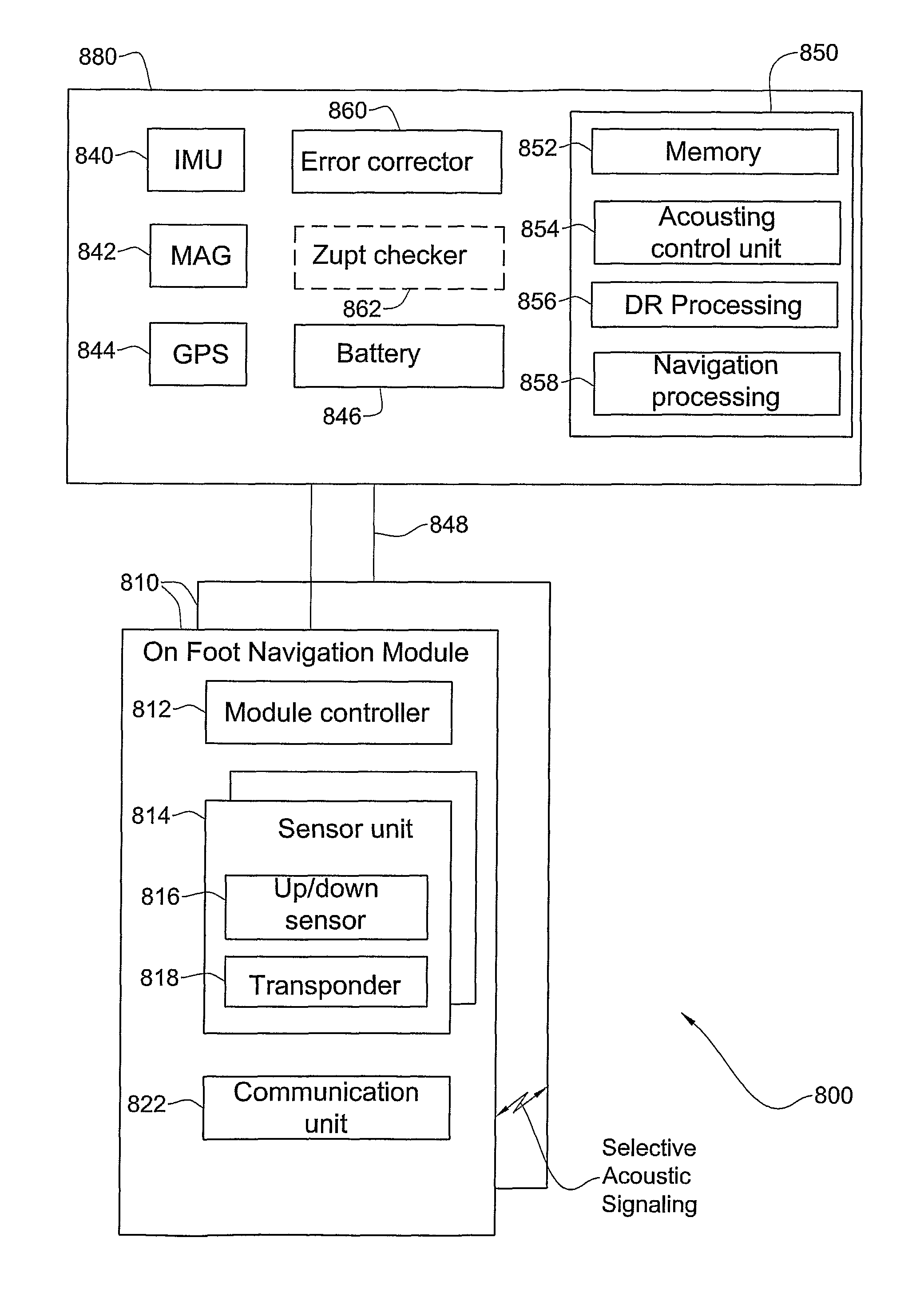
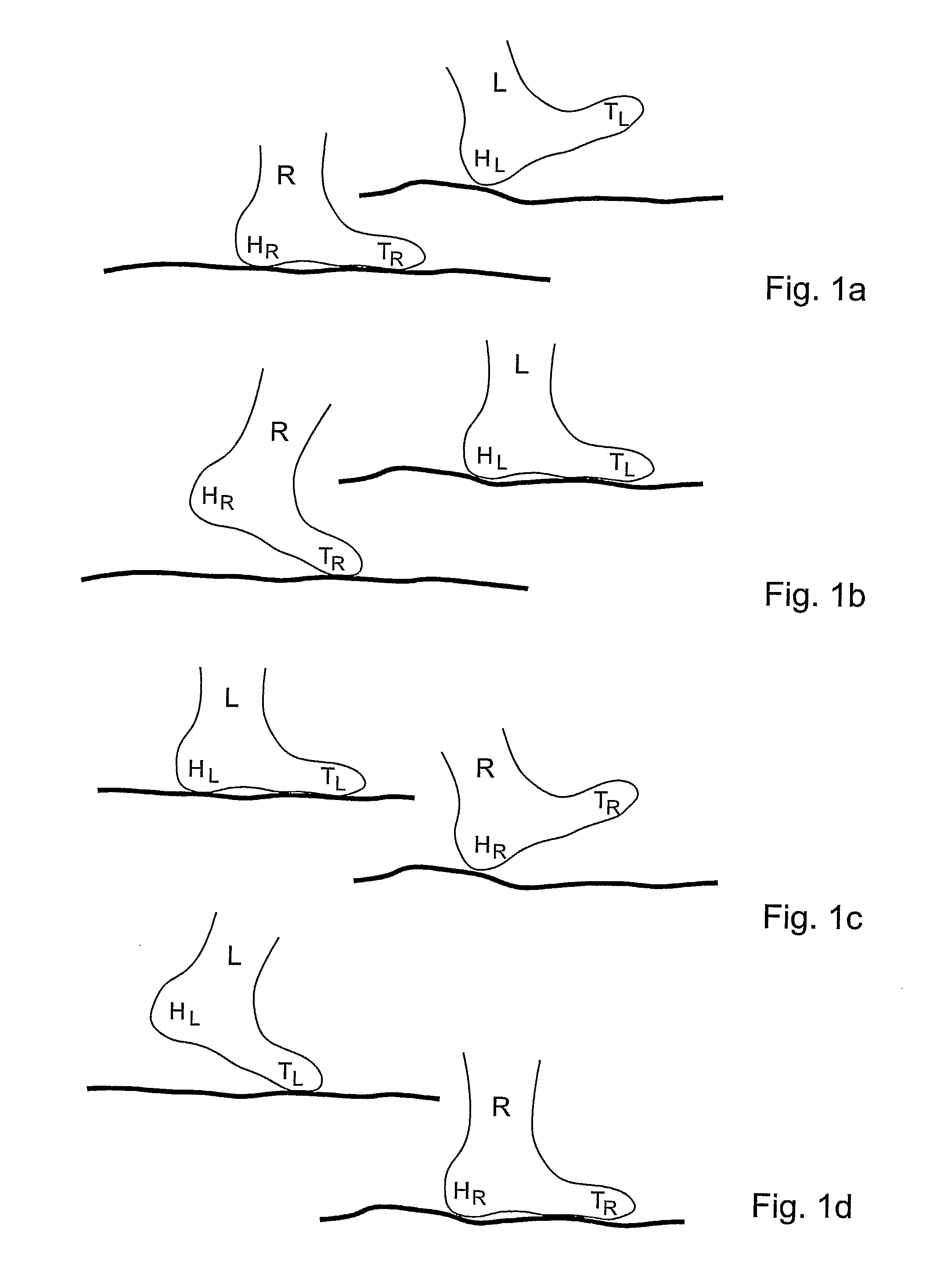
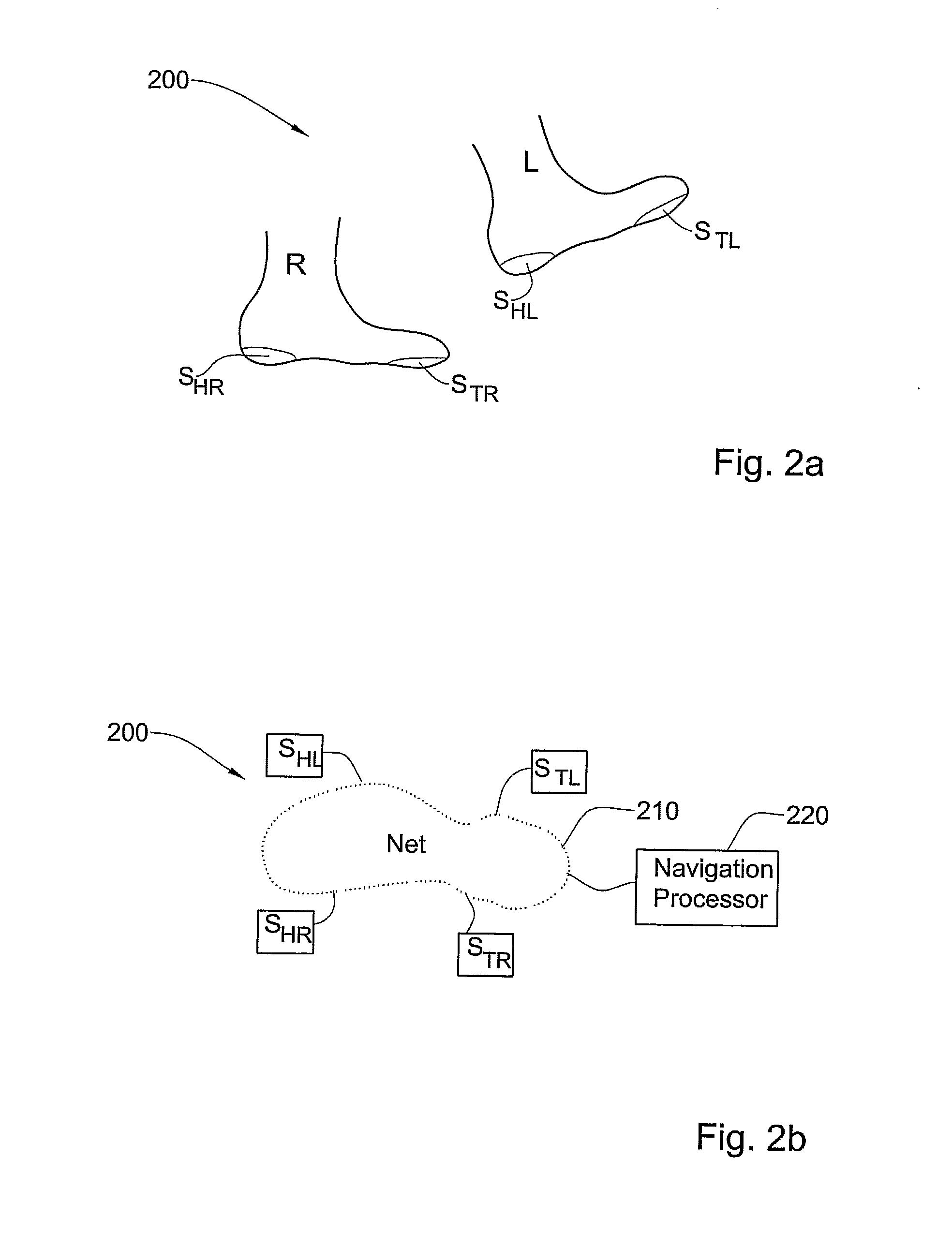
[0051]In accordance with a first aspect of the present invention there is provided a substantially autonomous on-foot dead-reckoning system and method utilizing, inter-alia, a sensor unit that comprises at least three or four sensors disposed on different locations on feet of a pedestrian, e.g. two sensors on the right foot and one or two sensors on the left foot. The sensors allow assessing the relative displacement of one foot with respect to the other. The resultant relative displacement data is considered and used in generating and transmitting a propagating signal (e.g. acoustic, infra-red, RF or other electromagnetic signal) from a transmitter / receiver associated with one sensor toward at least two a transmitter / receivers associated with other sensors, respectively. TOA information regarding receipt of the propagating signal by the at least two other transmitter / receivers is used in dead-reckoning navigation processing.

[0052]Thus, according to an embodiment of the invention th...


PUM


Abstract

An on-foot pedestrian navigation module useful for pedestrian navigation when operated with at least a control unit and another on-foot pedestrian navigation module, comprising (a) at least a first sensor unit and a second sensor unit, wherein each sensor unit including an up / down sensor adapted for sensing an ‘up’ condition and a ‘down’ condition associated with relative displacement of the module with respect to a surface, and a signal transmitter / receiver adapted, in response to an activation signal coming from a module controller, for generating a propagating signal (b) a module controller for controlling the operation of the module in response to a control signal coming from the control unit and (c) a communication unit for enabling said module to communicate with said at least the control unit and other module, thereby facilitating collecting motion data at the control unit and integrating the motion data with motion data coming from the other module, the motion data being indicative of a condition of each up / down sensor and receipt of the propagating signal by at least two sensor units of said other module, and wherein the motion data is useful for determining a momentary position of the pedestrian's foot during motion.

Description

FIELD OF THE INVENTION[0001]This invention relates to a pedestrian navigation system and method.BACKGROUND OF THE INVENTION[0002]Pedestrian tracking and positioning are required for a wide variety of navigation applications, such as search and rescue, military applications, sports and tourism navigation, commercial location-based services, and many more. Several pedestrian navigation aids are known that use low-cost, lightweight devices. There are known hand-held aids, as well as body-mounted aids e.g. devices mounted on head, shoulder, belt, shoe or foot.[0003]There are known pedestrian navigation aids that integrate several sensors and units e.g. Inertial Measurement Unit (IMU, e.g. microelectro-mechanical system (MEMS) including gyroscopes and accelerometers), a pedometer, a magnetometer, Global Positioning System (GPS and like systems), sonar and radar.[0004]An IMU solution typically suffers from errors accumulated due to inertial sensor's drifts: even a small inertial measureme...

Claims


Application Information

Patent Timeline
Patent Type & Authority Patents(United States)
IPC IPC(8): G01C22/00G01B7/14G01B11/14G01B17/00G01B21/00G06F19/00G06F17/40
CPCG01C22/006
Inventor CHERNOGUZ, NAHUMKAGAN, AVRAHAM
Owner ISRAEL AEROSPACE IND
Why Eureka
Try Eureka