Thru-hull light

a technology of thru-hull lights and tubes, which is applied in the field of thru-hull lights, can solve the problems of inability to permanently attach underwater lights to the exterior of the hull, tedious and cumbersome to lower lights on lines and cables from the deck of the vessel, and numerous problems encountered with prior art thru-hull lights

Active Publication Date: 2005-05-26
SEESCAN
View PDF51 Cites 63 Cited by
  • Summary
  • Abstract
  • Description
  • Claims
  • Application Information

AI Technical Summary

Benefits of technology

[0004] It is therefore an object of the present invention to provide a thru-hull light that will not overheat and damage the portion of a hull immediately adjacent to its cylindrical lamp housing.
[0005] It is another object of the present invention to provide a thru-hull light with an improved beam pattern that will provide both a long narrow beam and close up diff-use illumination adjacent the hull.
[0006] It is another object of the present invention to provide a thru-hull light with a protective transparent widow that is less subject to scratching from hull cleaning and breakage due to thermal shock and wave slap.

Problems solved by technology

However, in many cases a greater degree of illumination beneath the water surface is desired which can only be achieved if the light source is underwater.
It is not practical to permanently attach underwater lights to the exterior of the hull due to the excessive drag that would be created, not to mention the severe mechanical strains on such appendages at high velocities of vessel travel.
It is also tedious and cumbersome to lower lights on lines and cables from the deck of the vessel.
Numerous problems have been encountered with prior art thru-hull lights that have heretofore been commercialized for use with surface vessels.
Their high heat output can damage the portion of a fiberglass hull immediately adjacent to the cylindrical lamp housing.
Their beam patterns have not been optimized.
The windows of the prior art thru-hull lights are subject to scratching from hull cleaning and breakage due to thermal shock and wave slap.
The electrical circuits of the prior art thru-hull lights have not had any protection against water leakage, any protection against galvanic action that can lead to rapid and excessive corrosion of their metal parts, nor any power status or fault indicators.

Method used


Image

  • Thru-hull light
  • Thru-hull light
  • Thru-hull light

Examples


Embodiment Construction

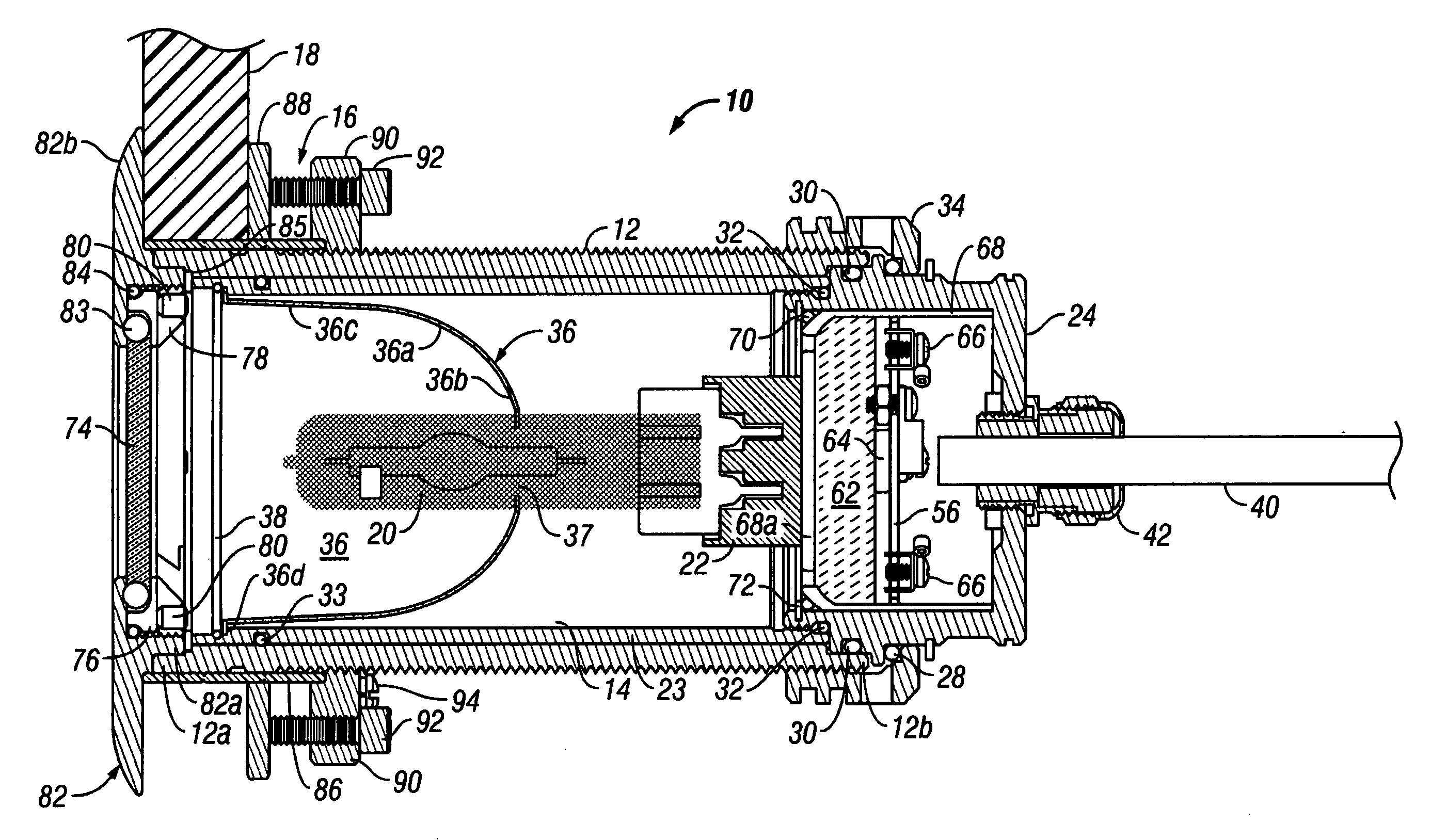
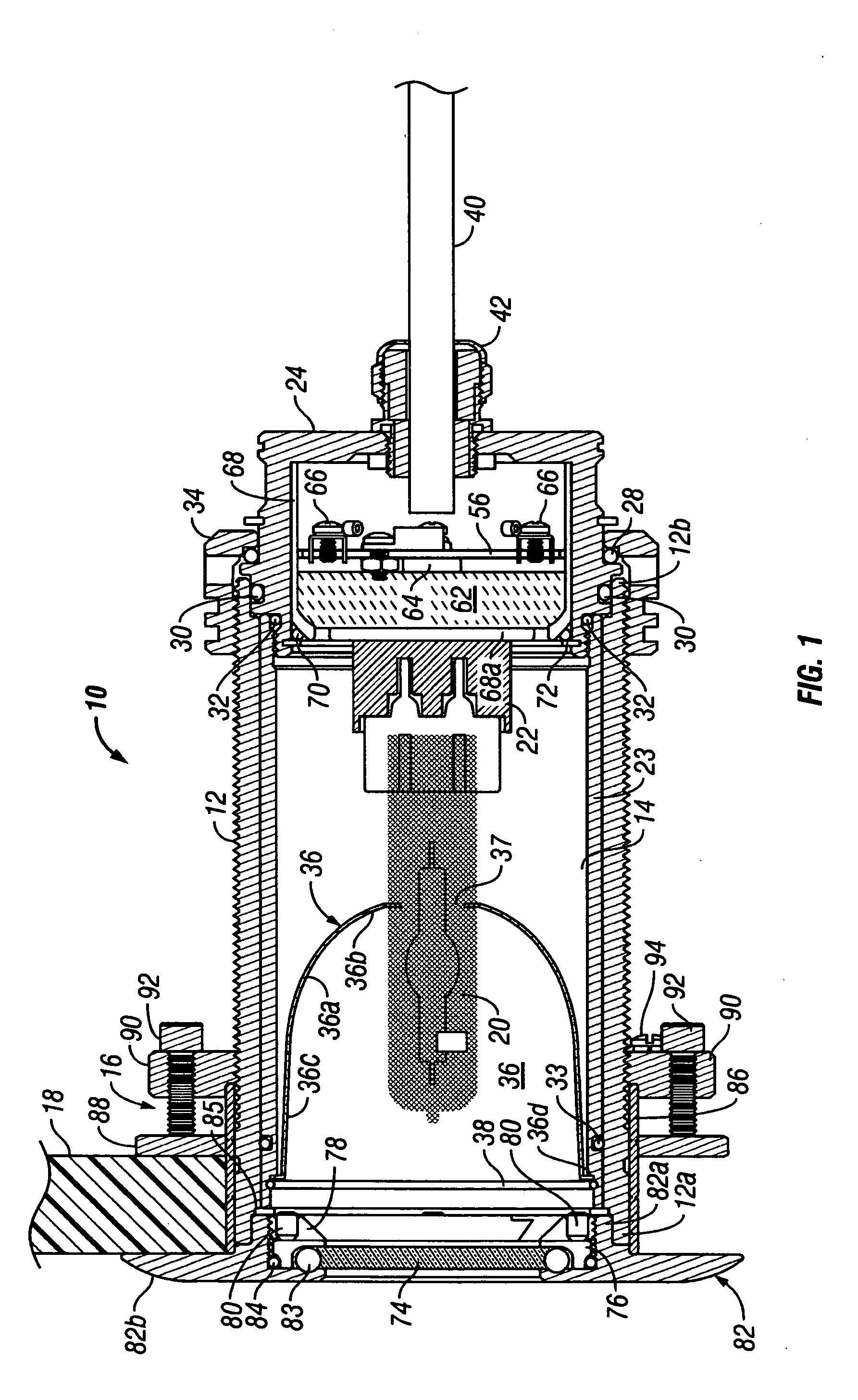
[0029] Referring to FIG. 1, a thru-hull light 10 includes an externally male threaded cylindrical lamp housing 12 made of a corrosion resistant material such as bronze, stainless steel or titanium and having a hollow interior 14 that communicates with a forward end 12a of the lamp housing 12. A thru-hull fitting assembly 16 is connected to the forward end 12a of the lamp housing 12 for mounting the forward end 12a of the lamp housing 12 in a hole in the hull 18 of a vessel in a water-tight fashion. Only a portion of the hull 18 is illustrated on one side of the sectional view of FIG. 1. The hull 18 could be made of fiberglass, steel, aluminum, wood, concrete or any other material used to construct rigid boat hulls. A high intensity discharge (HID) lamp 20 is plugged into a lamp socket 22 mounted in the interior 14 of the lamp housing 12. By way of example, the lamp 20 may be an OSRAM SYLVANIA® HID one hundred and fifty watt lamp with a color temperature of seven thousand K. The lamp...


PUM


Abstract

A thru-hull fitting assembly is connected to the forward end of a hollow lamp housing for mounting to a hole in the hull of a vessel in a water-tight fashion. An HID or other lamp is mounted in the lamp housing and is surrounded by a reflector which may have an outer elliptical section and an inner parabolic section. A protective transparent window extends across the forward end of the lamp housing and is sealed thereto. The window may be made of sapphire to provide improved heat dissipation and to resist scratching during hull cleaning and breakage due to thermal shock and wave slap. A circuit may be connected to the lamp to provide over-heat protection, leak detection, as well as fault and power status indicators. Alternate embodiments utilize a solid light pipe or a hollow reflective tube to convey light from the lamp to the protective window.

Description

FIELD OF THE INVENTION [0001] The present invention relates to illuminating devices, and more particularly, to lights that are designed to be mounted in a hole formed in the hull of a vessel for projecting a beam of light into the surrounding water. BACKGROUND OF THE INVENTION [0002] There are many night time situations in which it is desirable to illuminate the water around a ship, boat or other surface vessel from the vessel itself. This is often done with powerful search lights mounted on the bridge, cabin, deck or other structure of the vessel that illuminate the upper surface of the water. However, in many cases a greater degree of illumination beneath the water surface is desired which can only be achieved if the light source is underwater. For example, divers can more safely enter the water from a vessel and climb out of the water into a vessel during the night if the area beneath the hull of the vessel near the jump point, swim step or ladder is illuminated. Night time searc...

Claims


Application Information

Patent Timeline
Patent Type & Authority Applications(United States)
IPC IPC(8): B63B45/02B63C11/48F21V3/04F21V23/02F21V25/02F21V25/04F21V25/10F21V29/00F21V31/00
CPCB63B45/02B63C11/48F21V3/04F21V23/02F21V25/04F21V25/10F21V31/00F21V29/767F21W2107/20F21V31/005
Inventor OLSSON, MARKSIMMONS, ZACHARYPRSHA, JEFFREYGRAY, RONANMEREWETHER, RAY
Owner SEESCAN
Why Eureka
Try Eureka