Data transmission system and data transmission apparatus

a data transmission system and data transmission technology, applied in multi-frequency code systems, digital transmission, synchronisation signal speed/phase control, etc., can solve the problems of long startup time of pll circuit before being locked after being activated, large circuit scale and power consumption, etc., to reduce circuit scale and reduce electric power consumption.

Inactive Publication Date: 2005-05-26
SONY CORP
View PDF5 Cites 15 Cited by
  • Summary
  • Abstract
  • Description
  • Claims
  • Application Information

AI Technical Summary

Benefits of technology

[0006] It is therefore an object of the present invention to provide a data transmission system and a data transmission apparatus which can suitably be designed for a reduced circuit scale and reduced electric power consumption.
[0007] According to the present invention, a data transmission system has a first transmitter for transmitting data in synchronism with a first clock signal, and a second transmitter for receiving data from the first transmitter in synchronism with an output signal from a counter based on a second clock signal having a frequency higher than the first clock signal, the second transmitter having a clock shift compensator for controlling the number of pulses of the second clock signal depending on the result of comparison in phase between a phase reference signal based on the first clock signal and the output signal from the counter, thereby to correct the phase of the output signal from the counter to keep the output signal from the counter and the phase reference signal in phase with each other.
[0008] Therefore, if different transmission clock signals are used to send and receive data, then the phase difference between the clock signals is detected, and the number of pulses of one of the clock signals, i.e., the second clock signal, is controlled to correct the phase thereof for preventing the data from being destroyed or transmitted in error.

Problems solved by technology

The approach using the PLL circuit requires highly accurate analog circuit components such as VCO, etc., and hence poses problems in that the circuit scale and power consumption tend to be large.
In addition, the PLL circuit needs a long startup time before it is locked after being activated.
Therefore, the PLL method should desirably be limited to applications which will tolerate the above problems.
Short-distance data transmission applications which find the PLL circuit unsuitable for obtaining timing information employ a system, e.g., a DPA (Digital Phase Aligner), for transmitting timing information via a dedicated line.
However, the conventional circuit arrangements are liable to give rise to problems if efforts are made to reduce the circuit scale and reduce electric power consumption.
Consequently, the system tends to have a large hardware size and suffer increased electric power consumption.

Method used


Image

  • Data transmission system and data transmission apparatus
  • Data transmission system and data transmission apparatus
  • Data transmission system and data transmission apparatus

Examples


Embodiment Construction

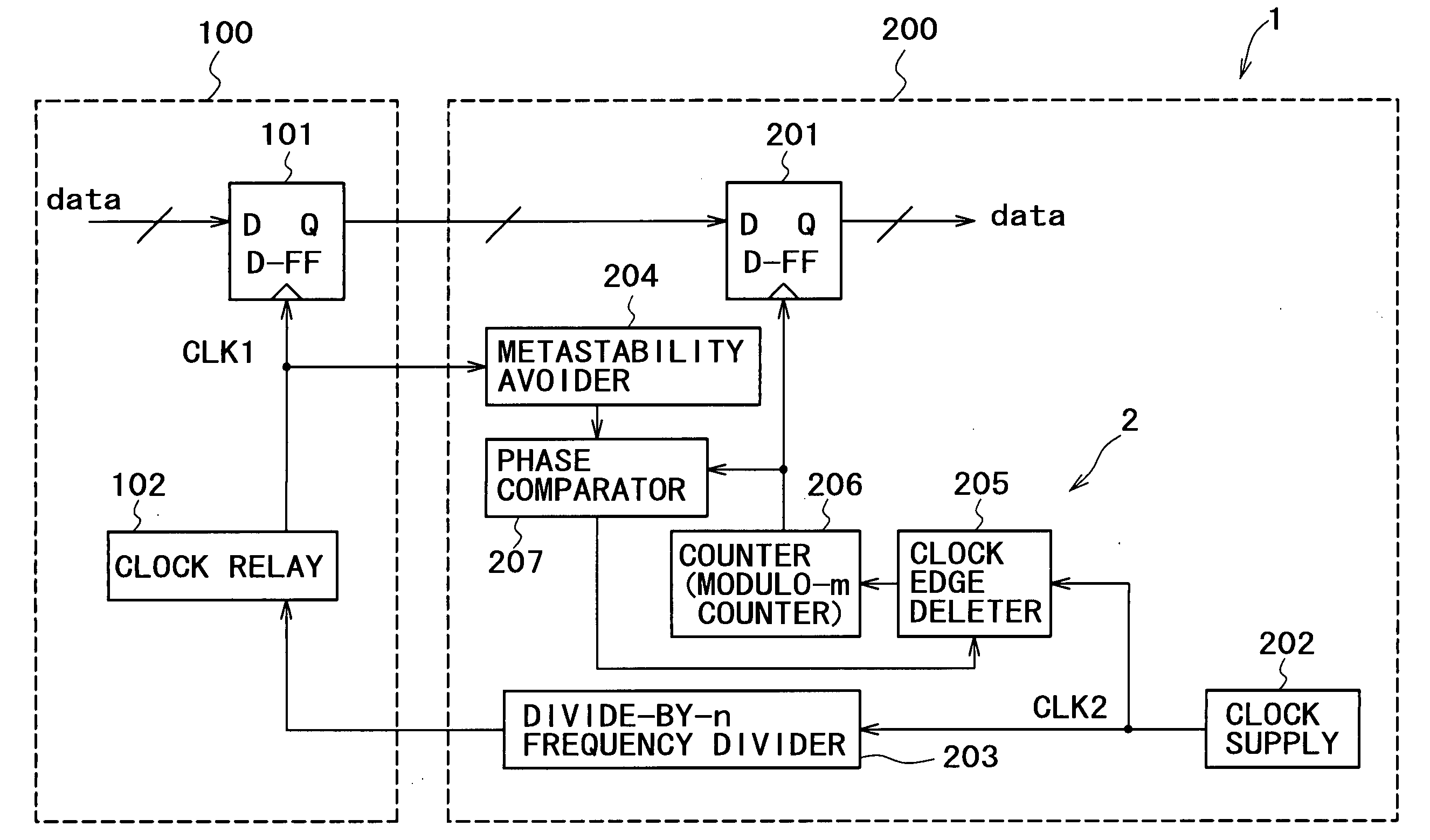
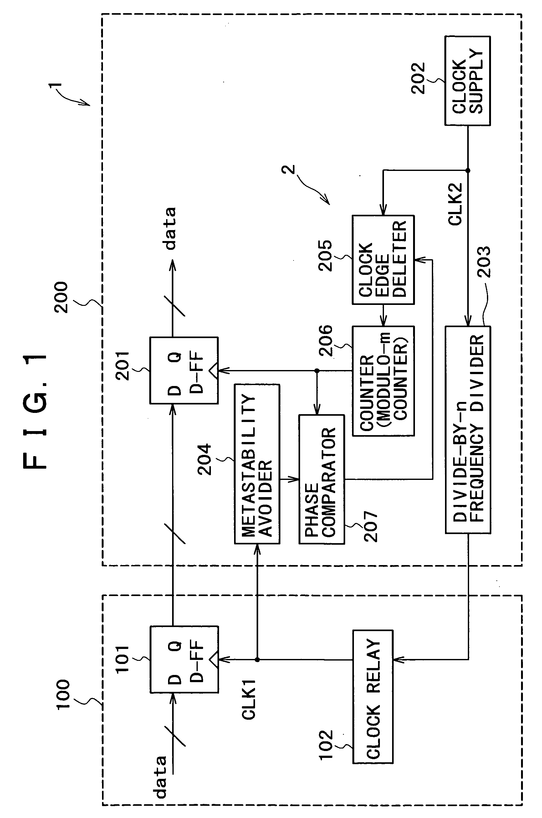
[0026] The present invention provides a clock shift compensating function without involving circuit complexities and circuit scale increases and a circuit arrangement suitable for a reduction in electric power consumption in a data transmission system and a data transmission apparatus for use in the data transmission system which perform unidirectional or bidirectional data communications between a first transmitter and a second transmitter.

[0027] The first transmitter and the second transmitter may be used in the following applications: [0028] (1) Data is transmitted between a plurality of transmitters are disposed in one circuit or apparatus. For example, data is transmitted between a circuit section and another circuit section in an LSI (Large-Scale Integration) circuit for use as a processor, a system chip, etc. [0029] (2) Data is transmitted between different circuits or apparatus of one type or different types. For example, data is transmitted from one transmission apparatus ...


PUM


Abstract

A data transmission system having a clock shift compensating function is designed for a reduced circuit scale and reduced electric power consumption. A data transmission D flip-flop in a transmitter is supplied with a clock signal for transmitting data from a clock delay. A transmitter has a data reception D flip-flop, a clock supply, a divide-by-n frequency divider for frequency-dividing a clock signal, and a metastability avoider for removing a metastable state from a clock signal received via the clock delay. The transmitter also has a phase comparator for comparing output signals from the metastability avoider and a modulo-m counter, and a clock edge deleter for controlling the number of pulses or edges of the clock signal from the clock supply depending on an output signal from the phase comparator. Pulses of the clock signal from the clock edge deleter are counted by the counter and supplied to the data reception D flip-flop.

Description

BACKGROUND OF THE INVENTION [0001] The present invention relates to a technique of reducing a circuit scale and saving electric power in a data transmission system and a data transmission apparatus which have a clock shift compensating function. [0002] For transmitting data on a communication line, it is generally necessary to transmit some timing-related information in order to differentiate individual data that is transmitted chronologically adjacent to each other. One widely used method is based on the fact that transmitted data change with time, and uses a PLL (Phase-Locked Loop) circuit to extract timing information of the data from the data that is received at a reception end. The approach using the PLL circuit requires highly accurate analog circuit components such as VCO, etc., and hence poses problems in that the circuit scale and power consumption tend to be large. In addition, the PLL circuit needs a long startup time before it is locked after being activated. Therefore, ...

Claims


Application Information

Patent Timeline
Patent Type & Authority Applications(United States)
IPC IPC(8): H04L25/40H04L7/00H04L7/033H04L7/04H04L27/26
CPCH04L7/0008H04L27/2675H04L27/2657H04L7/0331
Inventor KURODA, KEIICHIKOSHIMIZU, MIKIO
Owner SONY CORP
Why Eureka
Try Eureka