Composite constructions with oriented microstructure

a technology of oriented microstructure and composite construction, which is applied in the direction of magnetic bodies, soldering devices, manufacturing tools, etc., can solve the problems of gross brittle failure during use and limited application of cemented tungsten carbide, and achieve the effect of improving the properties of fracture toughness

Inactive Publication Date: 2005-05-26
SMITH INT INC
View PDF9 Cites 5 Cited by
  • Summary
  • Abstract
  • Description
  • Claims
  • Application Information

AI Technical Summary

Benefits of technology

[0008] Composite constructions having oriented microstructures, prepared according to principles of this invention, have improved properties of fracture toughness when compared to conventional cermet materials. In one embodiment of the invention, coated fibers, comprising a core formed from a hard phase material is surrounded by a shell formed from a binder phase material. The plurality of fibers are bundled together to produce a fibrous composite construction in the form of a rod. In another embodiment of the invention, monolithic sheets of the hard phase material and the binder phase material are stacked and arranged to produce a swirled composite in the form of a rod. In still another embodiment of the invention, sheets formed from coated fibers are arranged to produce a swirled composite.
[0010] Inserts for use in such drilling applications as roller cone rock bits and percussion hammer bits, and shear cutters for use in such drilling applications as drag bits, that are manufactured using conventional methods from these composite constructions exhibit increased fracture toughness due to the continuous binder phase around the hard phase of the composites. These binder phases increase the overall fracture toughness of the composite by blunting or deflecting the tip of a propagating crack.

Problems solved by technology

Although the fracture toughness of cemented tungsten carbide has been somewhat improved over the years, it is still a limiting factor in demanding industrial applications such as high penetration drilling, where cemented tungsten carbide inserts often exhibit gross brittle fracture that can lead to catastrophic failure.
Applications of cemented tungsten carbide are limited to this envelope.
However, this material also suffers from the same problem as cemented tungsten carbide, in that it also displays properties of low fracture toughness that can result in gross brittle failure during usage.

Method used


Image

  • Composite constructions with oriented microstructure
  • Composite constructions with oriented microstructure
  • Composite constructions with oriented microstructure

Examples


example no.1

EXAMPLE NO. 1

Fiber Composite Construction (WC—Co Core)

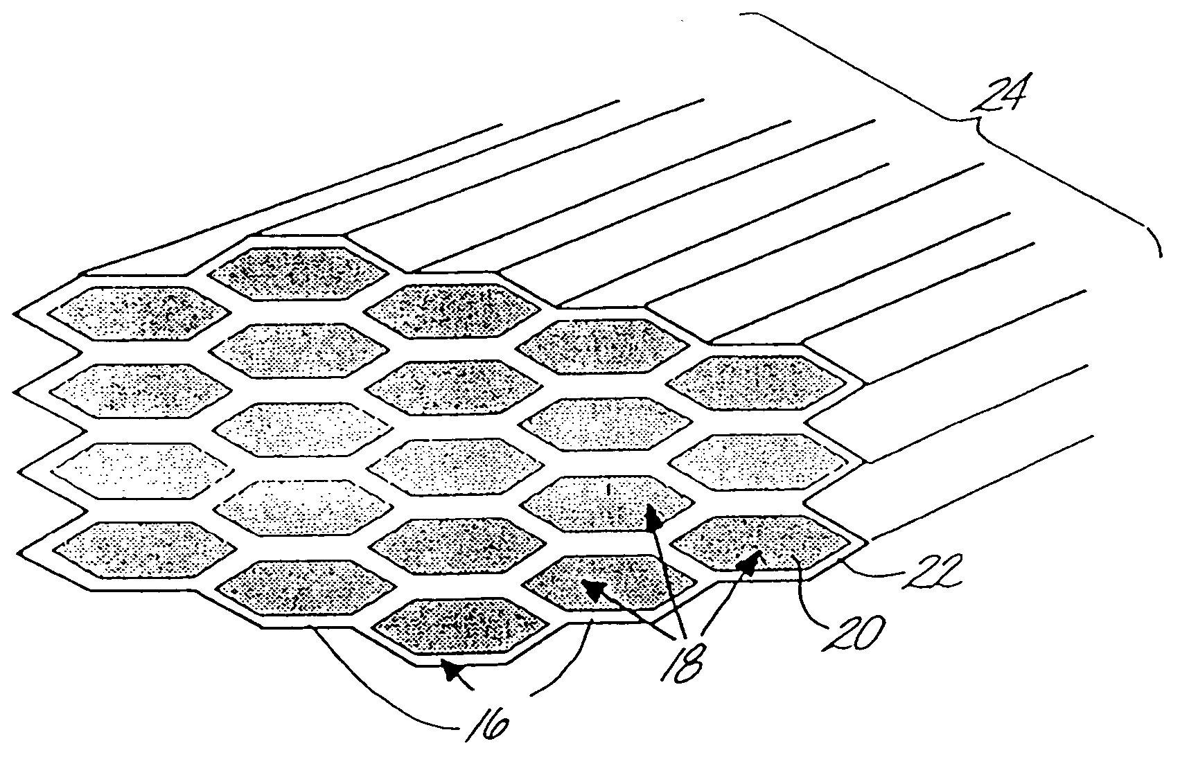
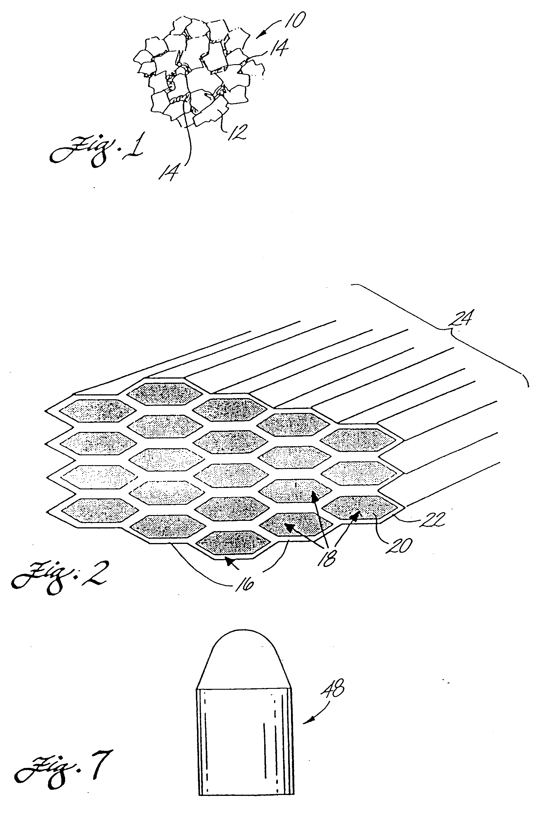
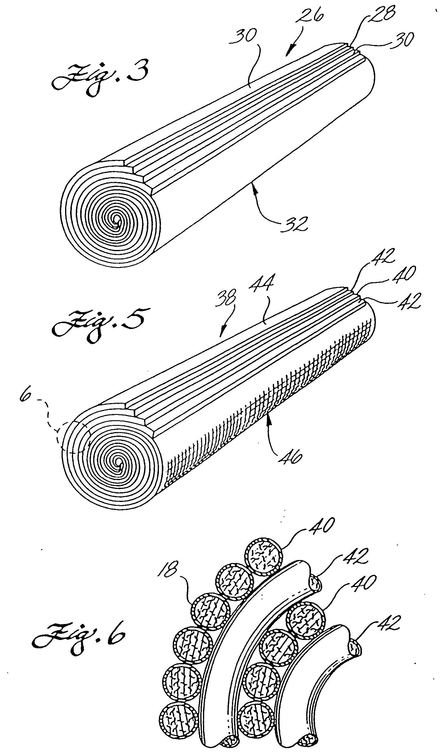
[0049] A fiber composite construction included a hard phase material core formed from WC—Co that was made from WC powder and Co powder, having an average grain size in the range of from about one to six micrometers. The WC—Co contained greater than about six percent by weight Co, based on the total weight of the WC—Co. The binder phase fiber shell was formed from Co, but alternatively could be formed from any of the above-identified metals or metal alloys. Each fiber had a diameter in the range of from 30 to 300 micrometers after consolidation.

example no.2

EXAMPLE NO. 2

Fiber Composite Construction (PCD Core)

[0050] A fiber composite construction included a core formed from PCD according to techniques described in U.S. Pat. Nos. 4,604,106; 4,694,918; 5,441,817; and 5,271,749. Diamond powder was used having an average grain size in the range of from about 4 to 100 micrometers, and was mixed with wax according to the referenced process, and was sintered to form the PCD. The binder phase fiber shell was formed from 411 carbide (i.e., WC comprising 11 percent by weight cobalt and having a WC grain size of approximately four micrometers). Alternatively, the fiber shell could be formed from any of the above-identified metals, metal alloys, and cermets. Each fiber had a diameter in the range of from 30 to 300 micrometers after consolidation.

example no.3

EXAMPLE NO. 3

Fiber Composite Construction (PCBN Core)

[0051] A fiber composite construction included a core formed from PCBN and WC—Co. The WC—Co was made from WC powder and Co powder having an average grain size in the range of from about one to six micrometers, and the PCBN was in the form of cBN powder having an average grain size in the range of from about 40 to 100 micrometers. The WC—Co contained greater than about six percent by weight Co, based on the total weight of the WC—Co. The core comprised in the range of from about 50 to 95 percent by volume PCBN based on the total volume of the core. Alternatively, the core can be formed from PCBN and TiC, or cBN and TiN+Al, or cBN and TiN+CO2Al9, where the core comprises in the range of from about two to ten percent by weight Al or CO2Al9 based on the total weight of the core.

[0052] The binder phase fiber shell was formed from WC—Co, made in the same manner described above for the core. Alternatively, the fiber shell could be form...


PUM

PropertyMeasurementUnit
particle sizeaaaaaaaaaa
thicknessaaaaaaaaaa
thicknessaaaaaaaaaa

Abstract

In one embodiment, composite constructions of the invention are in the form of a plurality of coated fibers bundled together to produce a fibrous composite construction in the form of a rod. Each fiber has a core formed from a hard phase material, that is surrounded by a shell formed from a binder phase material. In another embodiment of the invention, monolithic sheets of the hard phase material and the binder phase material are stacked and arranged to produce a swirled composite in the form of a rod. In still another embodiment of the invention, sheets formed from coated fibers are arranged to produce a swirled composite. Inserts for use in such drilling applications as roller cone rock bits and percussion hammer bits, and shear cutters for use in such drilling applications as drag bits, that are manufactured using conventional methods from these composite constructions exhibit increased fracture toughness due to the continuous binder phase around the hard phase of the composites. These binder phases increase the overall fracture toughness of the composite by blunting or deflecting the tip of a propagating crack.

Description

CROSS REFERENCE TO RELATED APPLICATIONS [0001] This application is a continuation of U.S. patent application Ser. No. 10 / 242,203, filed on Sep. 12, 2002 which is a continuation of U.S. patent application Ser. No. 09 / 549,974, filed on Apr. 14, 2000, now U.S. Pat. No. 6,451,442 which is a continuation of patent application Ser. No. 08 / 903,66, filed on Jul. 31, 1997, now U.S. Pat. No. 6,063,502 which claims benefit of U.S. Application No. 60 / 023,655, filed on Aug. 1, 1996.FIELD OF THE INVENTION [0002] This invention relates generally to composite constructions comprising a hard material phase and a relatively softer ductile material phase and, more particularly, to composite constructions that are designed having an oriented microstructure to provide improved properties of fracture toughness, when compared to conventional cermet materials such as cemented tungsten carbide, and polycrystalline diamond, cubic boron nitride, and the like. BACKGROUND OF THE INVENTION [0003] Cermet material...

Claims


Application Information

Patent Timeline
Patent Type & Authority Applications(United States)
IPC IPC(8): B22F7/06C22C47/00C22C47/02C22C47/14C22C49/00E21B10/52E21B10/56E21B10/567
CPCB22F7/06Y10T428/30B22F2005/002B22F2998/00B22F2998/10C22C47/00C22C47/025C22C47/04C22C47/068C22C47/14C22C49/00E21B10/52E21B10/56E21B10/567B22F2005/001Y10T428/12486Y10T428/12465Y10T428/12035B22F7/04B22F3/10B22F1/0003B22F3/20Y10T428/31504Y10T428/249927B22F1/09
Inventor SUE, J. ALBERTRAI, GHANSHYAMFANG, ZHIGANG
Owner SMITH INT INC
Why Eureka
Try Eureka