

Organic electroluminescent element
a technology of electroluminescent elements and organic materials, applied in the direction of discharge tube luminescnet screens, natural mineral layered products, transportation and packaging, etc., to achieve the effect of high luminous efficacy and reliability
- Summary
- Abstract
- Description
- Claims
- Application Information
AI Technical Summary
Benefits of technology
Problems solved by technology
Method used
Image

Examples
reference example 1
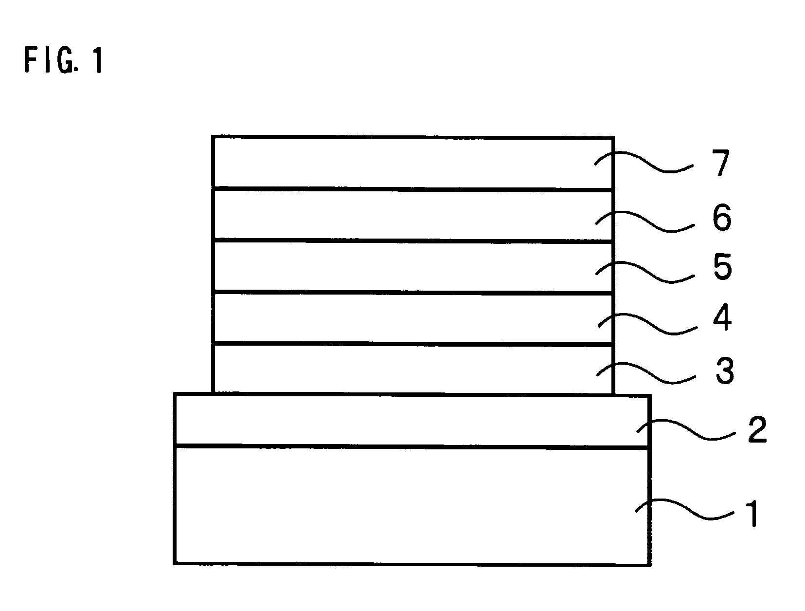
[0041] As is shown in Table 1, a transparent hole injection electrode (anode) 2 constituted of an indium-tin compound (hereinafter referred to as ITO) was formed on a glass substrate 1 and a hole injection layer 3 (film thickness: 10 nm) constituted of CuPc was formed on the hole injection electrode 2. A hole transfer layer 4 (film thickness: 75 nm) made of NPB was formed on the hole injection layer 3.
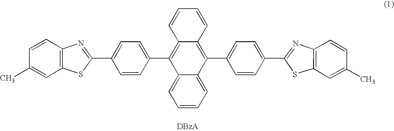
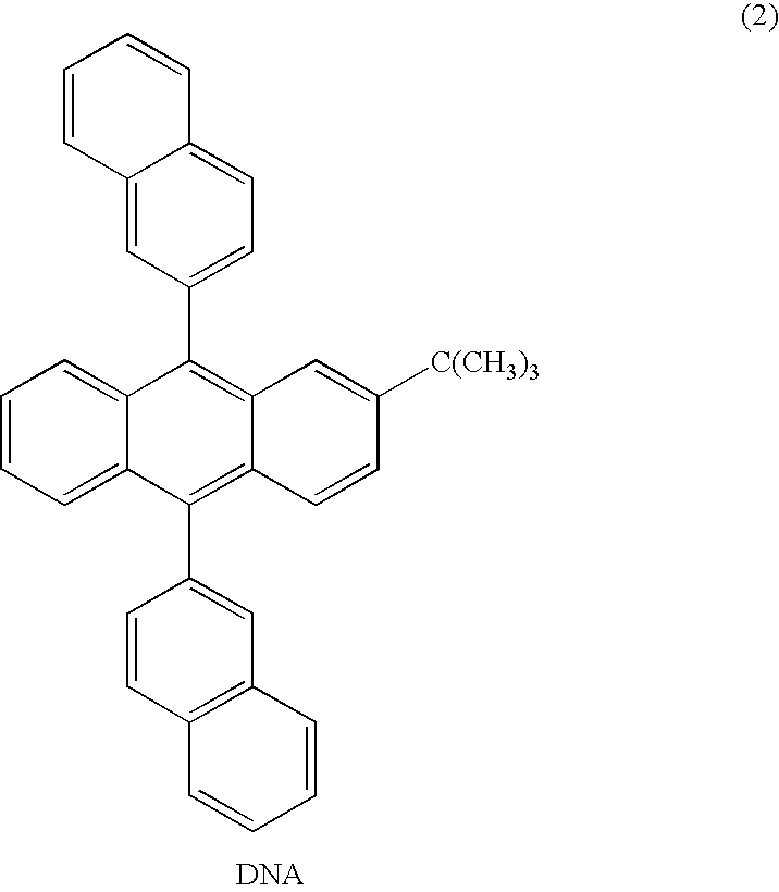
[0042] On the hole transfer layer 4, a blue light-emitting layer 5 prepared by compounding 2.5% by weight of DBzA as the light-emitting dopant and 7% by weight of NPB as the assist dopant in a host material constituted of DNA was formed.
[0043] An electron transfer layer 6 (film thickness: 10 nm) constituted of Alq was formed on the blue light-emitting layer 5. An electron injection electrode (cathode) 7 constituted of LiF (film thickness: 1 nm) and Al (film thickness: 200 nm) was formed on the electron transfer layer 6.
[0044] The aforementioned each layer was formed using a vacuum d...
reference example 2
[0050] In this Reference Example, as shown in Table 4, the blue light-emitting layer is constituted of a first blue light-emitting layer and a second blue light-emitting layer and only the first blue light-emitting layer is made to contain an assist dopant. The first blue light-emitting layer contains 7% by weight of NPB and 2.5% by weight of DBzA and has a film thickness of 10 nm. The second blue light-emitting layer contains 2.5% by weight of DBzA and has a film thickness of 30 nm.
TABLE 4HoleHoleElectronInjectionTransferFirst Blue Light-EmittingSecond Blue Light-EmittingTransferLayerLayerLayerLayerLayerCathode(Film(FilmFilmLight-FilmLight-(Film(FilmThickness:Thickness:ThicknessHostEmittingAssistThicknessHostEmittingAssistThick-Thickness:Anodenm)nm)(nm)MaterialDopantDopant(nm)MaterialDopantDopantness: nm)nm)Ref.ITOCuPc(10)NPB(75)10DNAFormulaNPB30DNAFormulaNoneAlq(10)LiF(1) / Ex. 2(1)(7% by(1)Al(200)DBzAweight)DBzA(2.5% by(2.5% byweight)weight)
[0051] The luminous characteristics of ...
example 1
[0053] In this example, as the light-emitting layer, in addition to the blue light-emitting layer, an orange light-emitting layer was further formed to produce a white organic electroluminescent element. The orange light-emitting layer was disposed on a hole transfer layer and the blue light-emitting layer was disposed on the orange light-emitting layer. The structure of each layer is shown in Table 6. The orange light-emitting layer used NPB as the host material and contained 3% by weight of rubrene as the light-emitting dopant as shown in Table 6. The thickness of the orange light-emitting layer was designed to be 10 nm. Also, the blue light-emitting layer was designed to have the same structure as that of Reference Example 1. The structural formula of rubrene is shown in the following.
[0054] The luminous characteristics of the manufactured white organic electroluminescent elements were evaluated in the same manner as in Reference Example 1. In this case, the luminous characteri...
PUM
| Property | Measurement | Unit |
|---|---|---|
| Wavelength | aaaaa | aaaaa |
| Wavelength | aaaaa | aaaaa |
| Thickness | aaaaa | aaaaa |
Abstract
Description
Claims
Application Information