Multistage fluid separation assembly and method

Inactive Publication Date: 2005-06-02
TWISTER BV
View PDF19 Cites 27 Cited by
  • Summary
  • Abstract
  • Description
  • Claims
  • Application Information

AI Technical Summary

Benefits of technology

[0021] The assembly may be provided with one or more ultrasonic vibration transducers for imposing ultrasonic vibrations at a frequency between 20 and 200 KHz on one or more components of

Problems solved by technology

This causes condensation and/or solidification of various components and formation of hydrate, wax and/or asphaltene deposits in the production tubulars and equipment.
A disadvantage of this known device is that the swirl imparting vanes are prone to fouling.
It has been found that the secondary condensables enriched fluid outlet of a supersonic cyclonic inertia separator may be connected to an LTX vessel, but that the high velocity of the injected

Method used


Image

  • Multistage fluid separation assembly and method
  • Multistage fluid separation assembly and method
  • Multistage fluid separation assembly and method

Examples


Embodiment Construction

[0030] Suitable embodiments of a multistage fluid separation assembly according to the present invention will be described in more detail with reference to the accompanying drawings wherein:

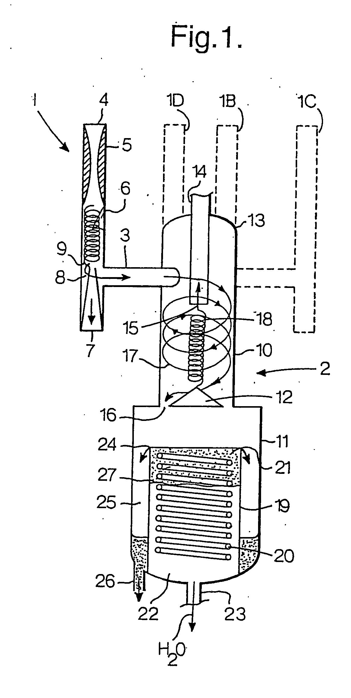
[0031]FIG. 1 is a schematic vertical split sectional view of a first suitable embodiment of a multistage fluid separation assembly according to the invention wherein four primary cyclonic inertia separators discharge a condensables enriched fluid mixture into a vertically oriented tubular secondary fluid separation vessel;

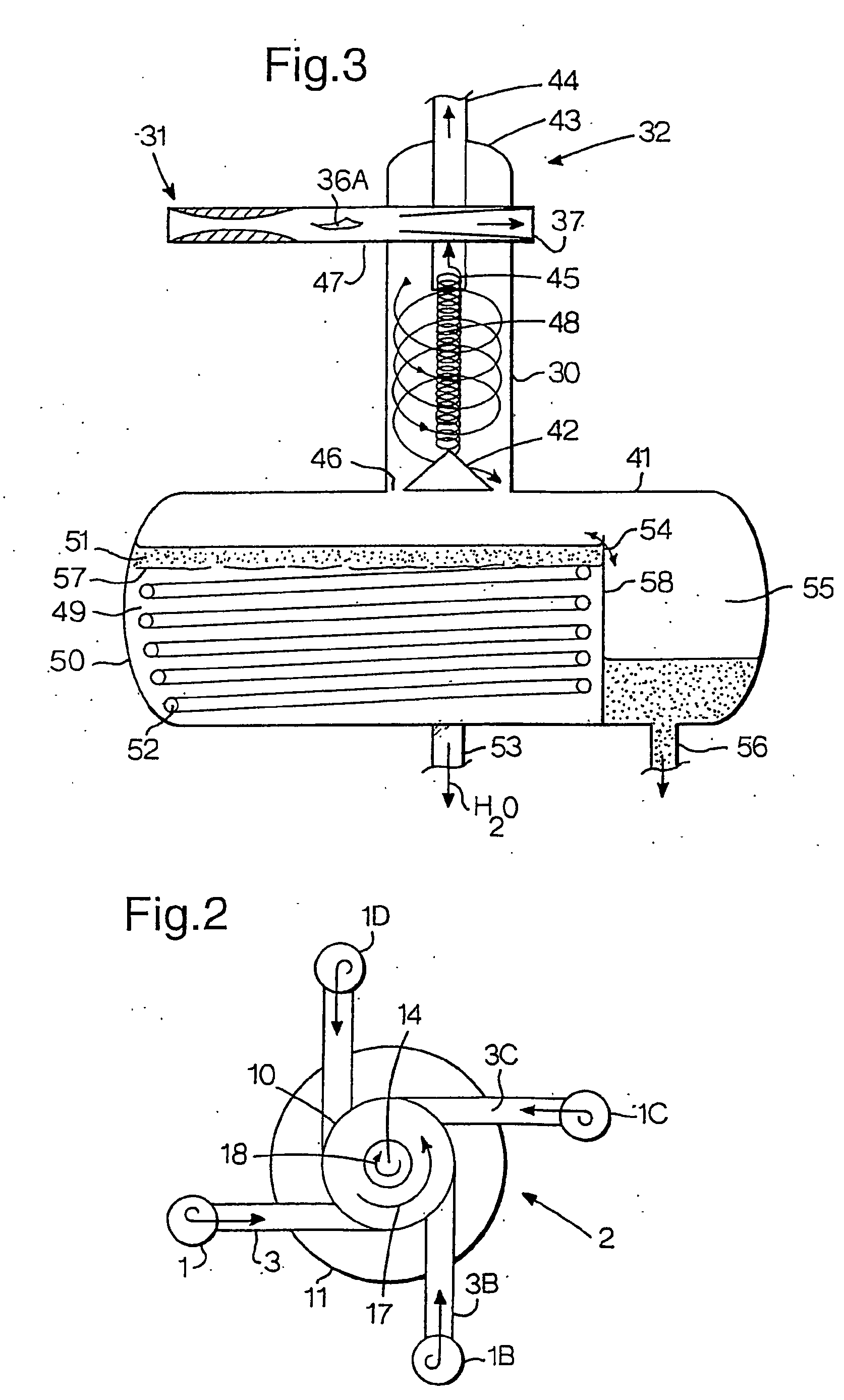
[0032]FIG. 2 is a top view of the multistage fluid separation assembly of FIG. 1;

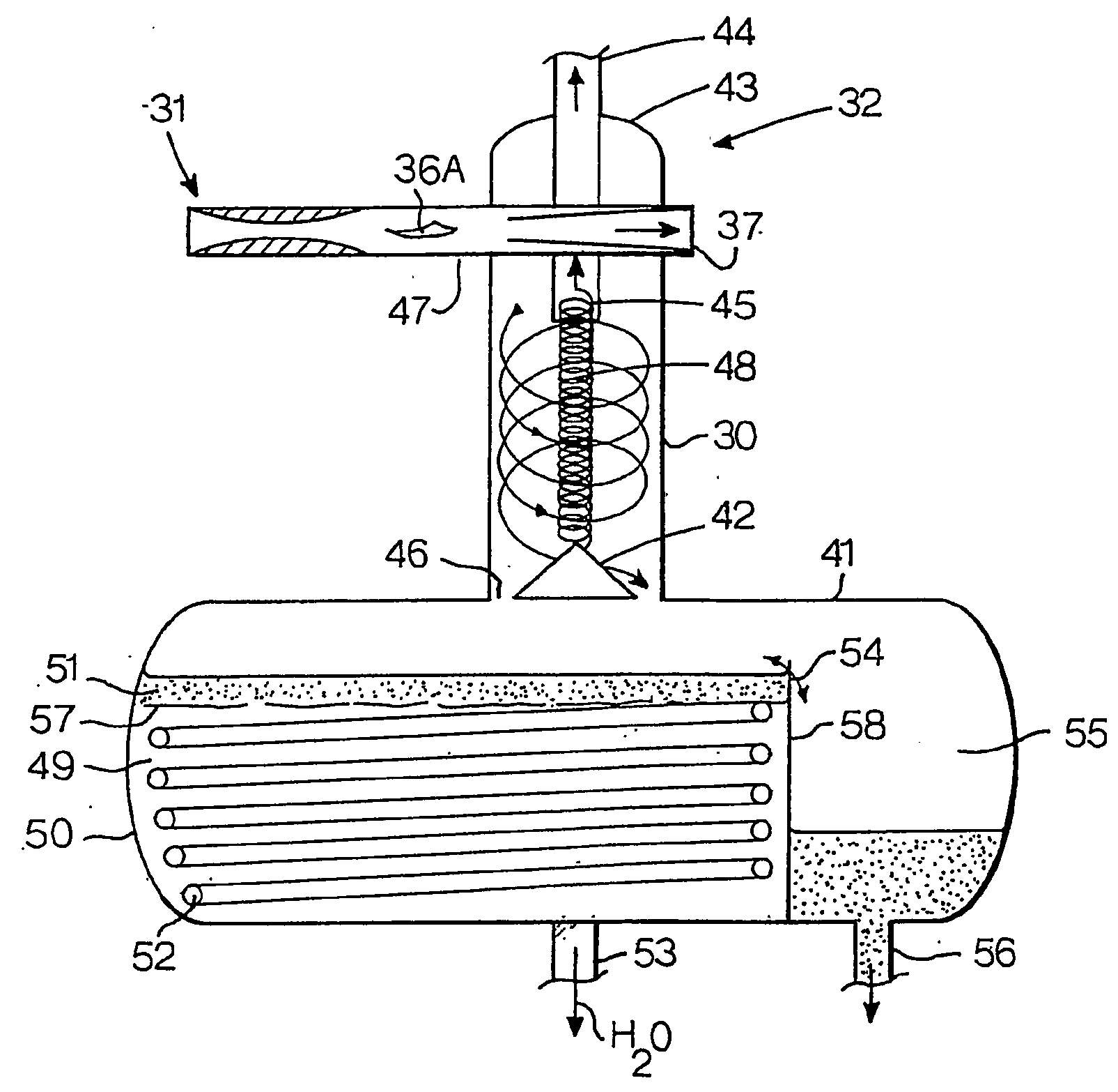
[0033]FIG. 3 is a schematic vertical split sectional view of another suitable embodiment of a multistage fluid separation assembly according to the invention wherein two primary cyclonic inertia separators discharge a condensables enriched fluid mixture into a horizontally oriented secondary fluid separation vessel;

[0034]FIG. 4 is a horizontal cross-sectional view of the multistage fluid separat...


PUM

PropertyMeasurementUnit
Temperatureaaaaaaaaaa
Lengthaaaaaaaaaa

Abstract

A multistage fluid separation assembly is disclosed, which includes one or more primary gas cooling devices which each have liquefied and/or solidified condensables enriched fluid outlet, and, a secondary fluid separation vessel having a tubular vertical section. The vessel is connected to the condensables enriched fluid outlet of the primary gas cooling device(s) via a tangential conduit which injects the condensables enriched fluid tangentially into the tubular section such that a tertiary stream of liquified and/or solidified condensables is induced by gravity and centrifugal forces to swirl in downward direction alongside the inner surface of the tubular section into a liquid collecting tank at or near the bottom of the vessel for collecting a tertiary mixture of liquified and/or solidified condensables. The tank is provided with one or more heaters for heating the tertiary mixture to reduce the amount of solidified condensables, such as wax, paraffins and hydrates, and with one or more liquid outlets.

Description

BACKGROUND OF THE INVENTION [0001] The invention relates to a multistage fluid separation assembly and method. [0002] In many oil and / or gas production wells the well effluents may comprise complex fluid mixtures which contain crude oil, natural gas (methane), water, brine, condensates, sulphur, hydrogen sulphide and other components. [0003] During production the well effluents expand and generally cool down from reservoir temperatures which may be between 100 and 200 degrees Celsius to significantly lower atmospheric or submarine temperatures. [0004] This causes condensation and / or solidification of various components and formation of hydrate, wax and / or asphaltene deposits in the production tubulars and equipment. [0005] It is known from U.S. Pat. No. 4,026,120 to remove condensable and / or solidifiable components from the produced well effluents at the wellhead by cooling down the well effluents in a choke and injecting the cooled well effluents into a so called ‘LTX’ (Low Tempera...

Claims


Application Information

Patent Timeline
IPC IPC(8): B01D45/12B01D45/16B04C5/185B04C5/20B04C5/26B04C7/00B04C9/00
CPCB01D45/12B01D45/16B04C9/00B04C5/20B04C7/00B04C5/185B04C5/26
Inventor BAKKER, HILLEGONDATER HAAR, MAX ROBERT ANTHONYOKIMOTO, FRED TOSHIOTJEENK WILLINK, CORNELIS ANTONIE
Owner TWISTER BV
Why Eureka
Try Eureka