Fuel gauge for fuel cartridges

a fuel gauge and cartridge technology, applied in the direction of fuel cells, volume measurement apparatus/methods, volume/mass flow by differential pressure, etc., can solve the problems of inability to make enough small for consumer electronic devices, large storage tanks are typically required, and the fuel gauge does not function at any fuel cartridge orientation

Active Publication Date: 2005-06-02
INTELLIGENT ENERGY LTD
View PDF40 Cites 31 Cited by
  • Summary
  • Abstract
  • Description
  • Claims
  • Application Information

AI Technical Summary

Benefits of technology

[0017] The readable property can be the resistance of a semi-conducting resistor. Preferably, the semi-conducting resistor is a thermistor. The thermistor is located adjacent to the fuel, and preferably located adjacent to a liner containing the fuel. Alternatively, the thermistor is located within the fuel. The electrical circuit can send an electrical current either intermittently or continuously to the thermistor to gage the amount of remaining fuel.
[0018] The readable property can also be the resistance of a bi-metal resistor. Preferably, the bi-metal resistor is a thermocouple. The thermocouple is located adjacent to the fuel, and preferably located adjacent to a liner containing the fuel. Alternatively, the thermocouple is located within the fuel. The electrical circuit can send an electrical current either intermittently or continuously to the thermocouple to gage the amount of remaining fuel.
[0019] The readable property can also be an oscillating magnetic field generated by an inductive sensor. A second sensor interferes with the magnetic field causing eddy currents to form. The inductive sensor is preferably located on the fuel cell or the electronic device and the second sensor is spaced apart from the inductive sensor. The distance between the inductive sensor and the second sensor, which correlates to the remaining fuel, is related to the strength of the oscillating magnetic field.

Problems solved by technology

Compressed hydrogen is generally kept under high pressure and is therefore difficult to handle.
Furthermore, large storage tanks are typically required and cannot be made sufficiently small for consumer electronic devices.
The prior art, however, does not discloses a fuel gauge that functions at any fuel cartridge orientation.

Method used


Image

  • Fuel gauge for fuel cartridges
  • Fuel gauge for fuel cartridges
  • Fuel gauge for fuel cartridges

Examples


Embodiment Construction

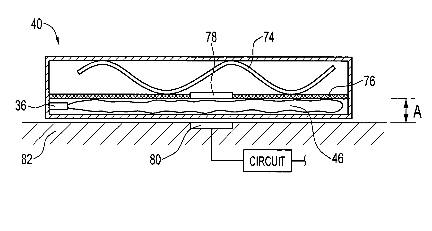
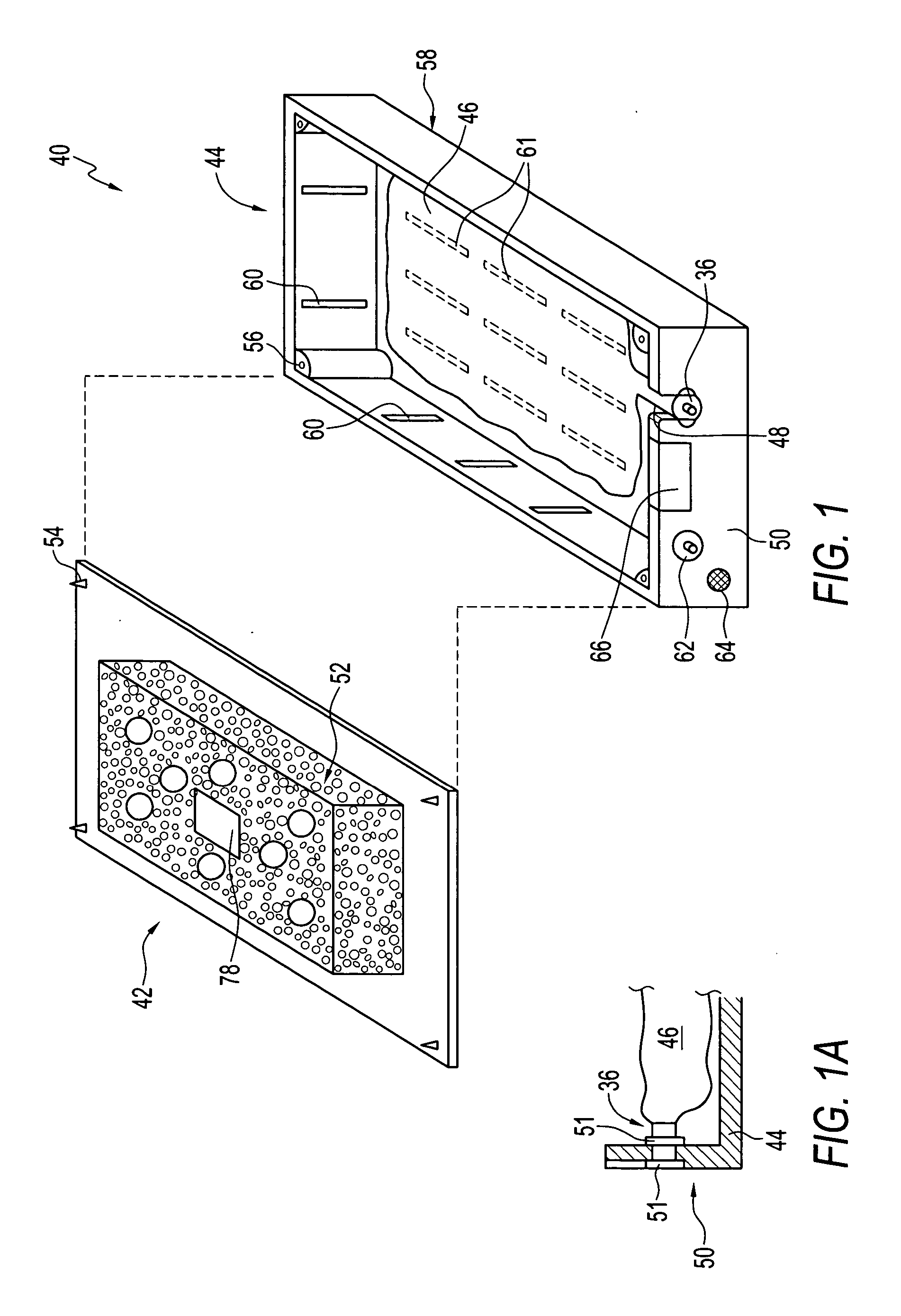
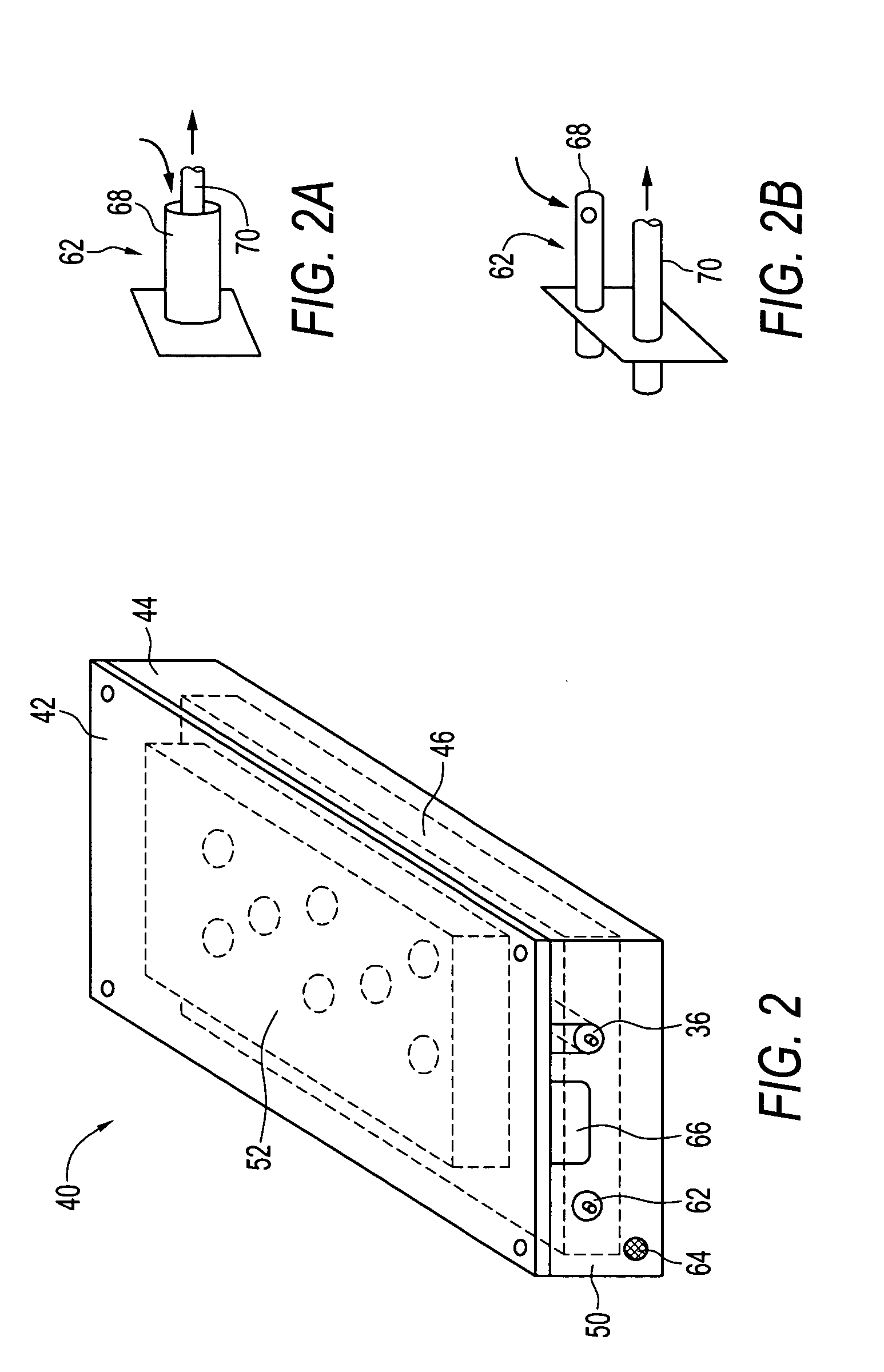
[0027] As illustrated in the accompanying drawings and discussed in detail below, the present invention is directed to a fuel supply, which stores fuel cell fuels such as methanol and water, methanol / water mixture, methanol / water mixtures of varying concentrations or pure methanol. Methanol is usable in many types of fuel cells, e.g., DMFC, enzyme fuel cell, reformat fuel cell, among others. The fuel supply may contain other types of fuel cell fuels, such as ethanol or alcohols, chemicals that can be reformatted into hydrogen, or other chemicals that may improve the performance or efficiency of fuel cells. Fuels also include potassium hydroxide (KOH) electrolyte, which is usable with metal fuel cells or alkali fuel cells, and can be stored in fuel supplies. For metal fuel cells, fuel is in the form of fluid borne zinc particles immersed in a KOH electrolytic reaction solution, and the anodes within the cell cavities are particulate anodes formed of the zinc particles. KOH electrolyt...


PUM

PropertyMeasurementUnit
thicknessaaaaaaaaaa
dielectric constantsaaaaaaaaaa

Abstract

Fuel gauges for fuel supplies for fuel cells are disclosed. Each fuel gauge has a property that is readable by an electrical circuit. These properties are related to the remaining fuel in the fuel supplies. These properties include, but are not limited to, electrical capacitance, magnetic, semi-conducting resistance, bi-metal resistance, and oscillating magnetic field. These fuel gauges are functional at any fuel supply orientation.

Description

FIELD OF THE INVENTION [0001] This invention generally relates to a fuel gauge for cartridges supplying fuel to various fuel cells. BACKGROUND OF THE INVENTION [0002] Fuel cells are devices that directly convert chemical energy of reactants, i.e., fuel and oxidant, into direct current (DC) electricity. For an increasing number of applications, fuel cells are more efficient than conventional power generation, such as combustion of fossil fuel and more efficient than portable power storage, such as lithium-ion batteries. [0003] In general, fuel cell technologies include a variety of different fuel cells, such as alkali fuel cells, polymer electrolyte fuel cells, phosphoric acid fuel cells, molten carbonate fuel cells, solid oxide fuel cells and enzyme fuel cells. Today's more important fuel cells can be divided into three general categories, namely, fuel cells utilizing compressed hydrogen (H2) as fuel; proton exchange membrane (PEM) fuel cells that use methanol (CH3OH), sodium borohy...

Claims


Application Information

Patent Timeline
Patent Type & Authority Applications(United States)
IPC IPC(8): G01F23/26H01M8/04
CPCG01F23/263G01F23/265G01F23/268H01M8/04089Y02E60/50H01M8/04201H01M8/04208H01M8/04604H01M8/04634H01M8/04186G01F23/18
Inventor CURELLO, ANDREW J.FAIRBANKS, FLOYDLOONIS, CHARLES
Owner INTELLIGENT ENERGY LTD
Why Eureka
Try Eureka