Potential fixing device, potential fixing method, and capacitance mearuing instrument

a technology of potential fixing and capacitance measurement, which is applied in the direction of instruments, frequency response correction, one-port networks, etc., can solve the problems of circuit not operating normally, circuit electric potential of signal lines, and circuit size increase, so as to achieve accurate capacitance measurement, avoid the effect of reducing the sensing of the capacitance measurement apparatus and facilitating the execution of the capacitance measuremen

Inactive Publication Date: 2005-06-02
TOKYO ELECTRON LTD +1
View PDF9 Cites 4 Cited by
  • Summary
  • Abstract
  • Description
  • Claims
  • Application Information

AI Technical Summary

Benefits of technology

[0031] In the electric potential fixing method in the above further other aspect, when fixing the electric potential of the connection line between the first capacitance and the second capacitance, by setting up the output electric potential applied to the connection line to be equal to the electric potential of the operation signal applied to the connection line between the two capacitances, it is possible to prevent the combined total amount of electric charge from changing. Additionally, by fixing the electric potential by the output electric potential divided using at least two high impedances, it is possible by the high impedances to prevent effectively part of the electric current that flows to the connection line from flowing to the side of the high impedance. This can also prevents the combined total amount...

Problems solved by technology

Consequently, it is necessary to set up newly a processing circuit that does not have the frequency characteristic in a subsequent stage, and therefore there is a problem that the size of the circuit becomes large.
For this reason, the electric potential of the signal line 117 becomes unstable and there is a disadvantage that the circuit does not operate normally such as the circuit output being saturated with the power voltage.
I...

Method used


Image

  • Potential fixing device, potential fixing method, and capacitance mearuing instrument
  • Potential fixing device, potential fixing method, and capacitance mearuing instrument
  • Potential fixing device, potential fixing method, and capacitance mearuing instrument

Examples


first embodiment

The First Embodiment

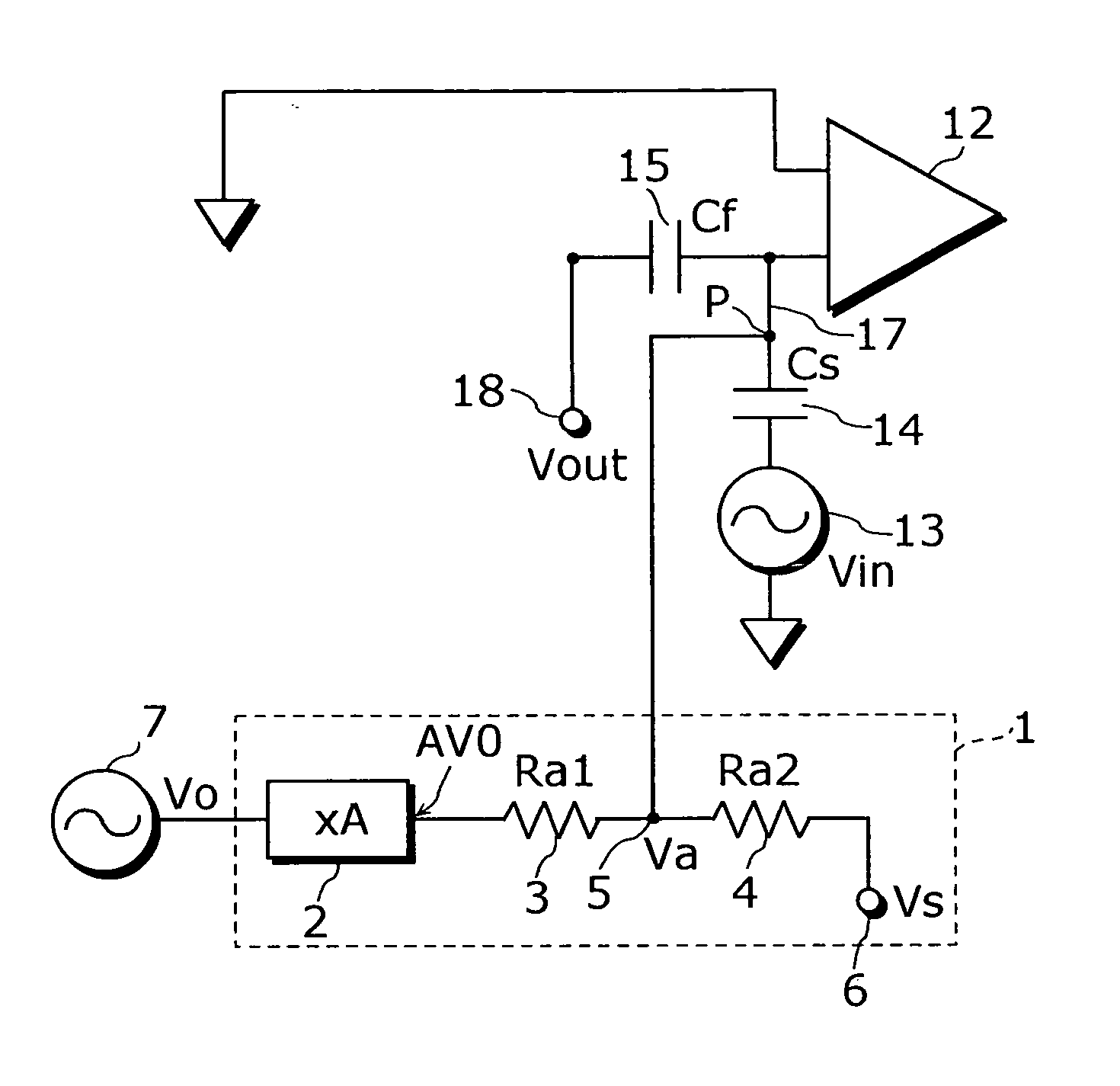
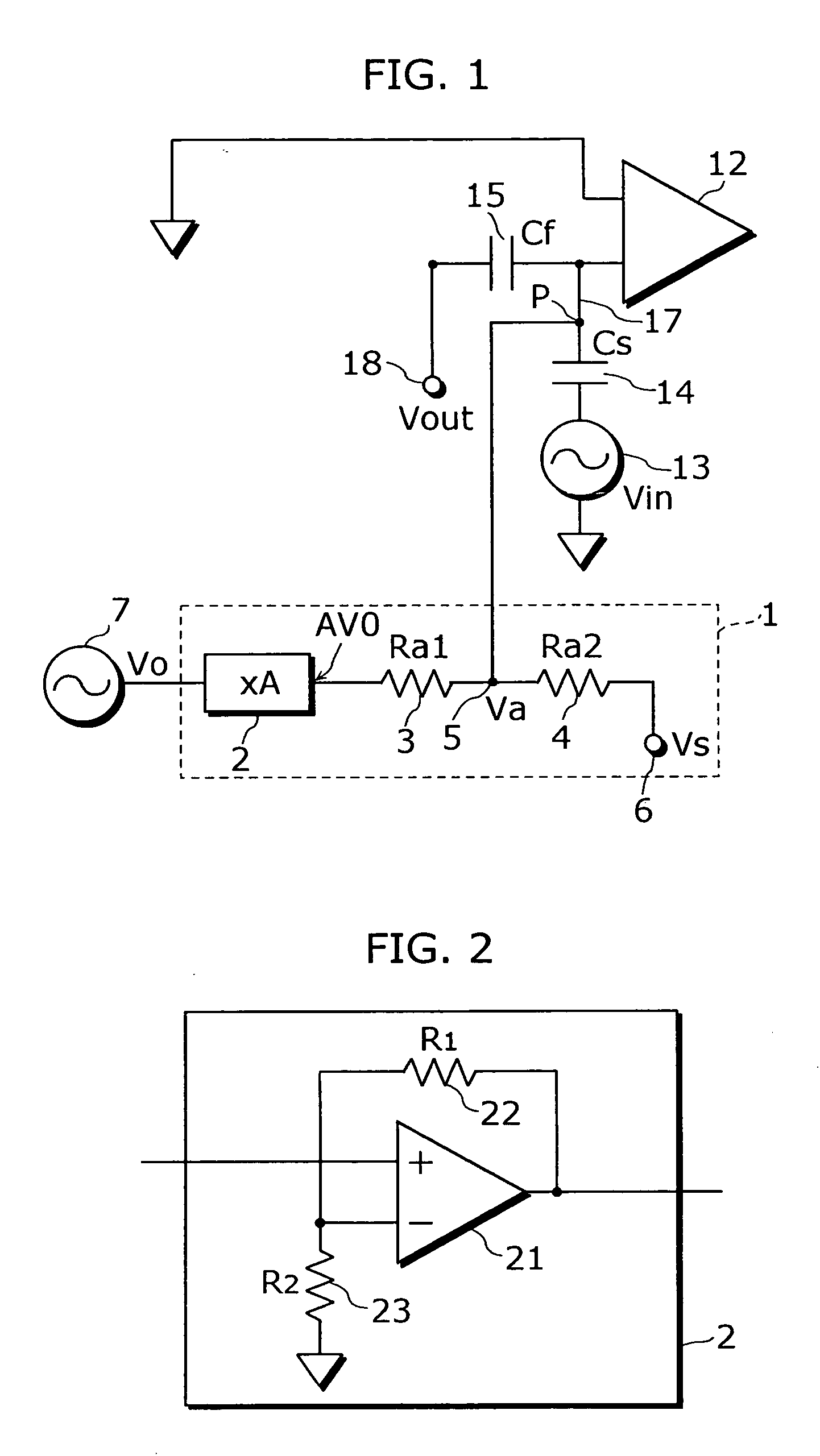
[0041]FIG. 1 is a circuit diagram showing a capacitance measurement apparatus including an electric potential fixing apparatus according to the first embodiment of the present invention. FIG. 2 is a circuit diagram showing an example of the internal configuration of an amplifier in the electric potential fixing apparatus of the first embodiment shown in FIG. 1.

[0042] First, the configuration of the capacitance measurement apparatus including the electric potential fixing apparatus according to the first embodiment is explained with reference to FIG. 1 and FIG. 2. The capacitance measurement apparatus of the first embodiment includes an operation amplifying circuit 12, an AC voltage generation apparatus 13, a measuring capacitance 14 which has an electrostatic capacitance Cs and a fixed capacitance 15, which has a capacitance value Cf, as feedback impedance. By the way, the operational amplifying circuit 12 is an example of “the first operational amplifier” of th...

second embodiment

The Second Embodiment

[0055]FIG. 3 is a circuit diagram showing the capacitance measurement apparatus equipped with the electric potential fixing apparatus including the voltage division circuit according to the second embodiment of the present invention. Referring to FIG. 3, the voltage supply circuit 1 of the second embodiment shows an example that the AC voltage generation apparatus 13, which applies the operation signal Vin to the signal line 17, is connected to the input side of the amplifier 2, instead of the AC voltage generation apparatus 7, in the configuration of the above-described first embodiment. By the way, the other configuration than the second embodiment is same as that of the above-described first embodiment.

[0056] In the second embodiment, as is described above, by connecting the AC voltage generation apparatus 13 that applies the operation signal Vin to the signal line 17 to the input side of the amplifier 2, the AC voltage generation apparatus 7 can be omitted ...

third embodiment

The Third Embodiment

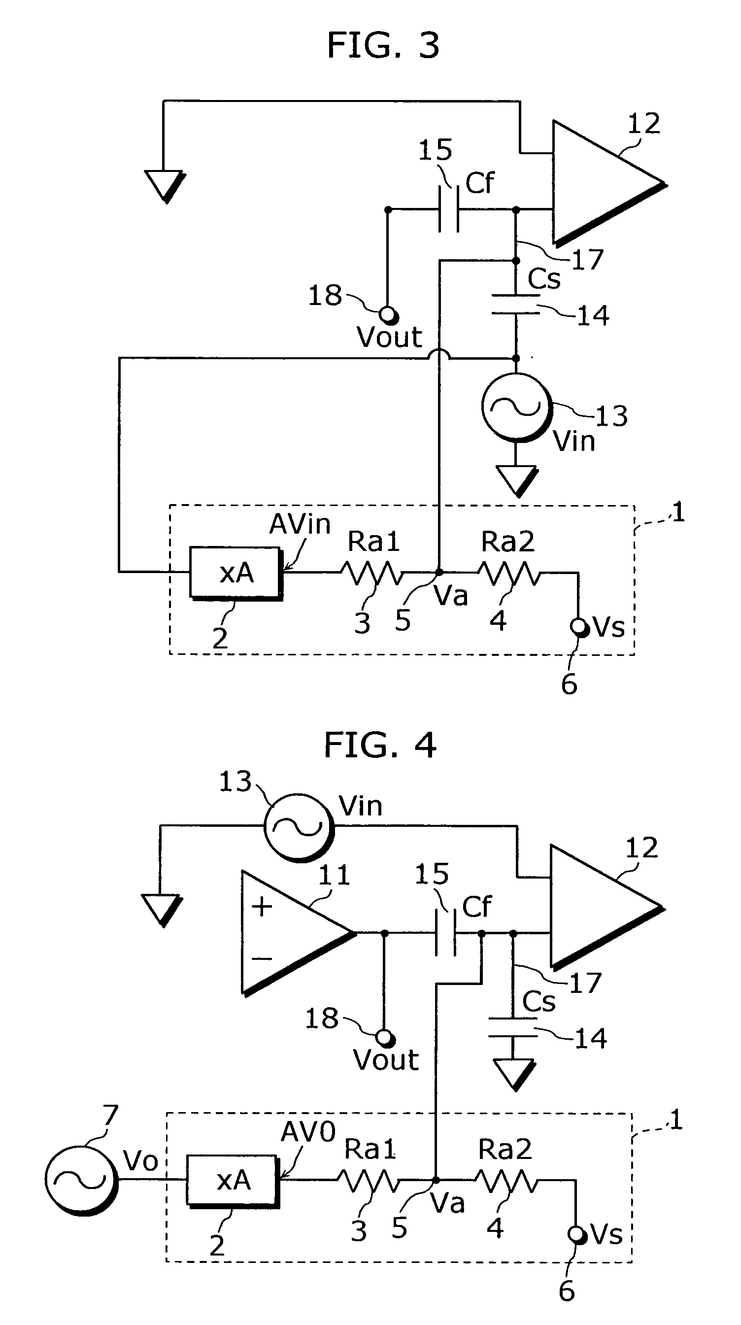
[0059]FIG. 4 is a circuit diagram showing the capacitance measurement apparatus including the electric potential fixing apparatus according to the third embodiment of the present invention.

[0060] First, referring to FIG. 4, the configuration of the capacitance measurement apparatus including the electric potential fixing apparatus according to the third embodiment is explained. The capacitance measurement apparatus according to the third embodiment includes an operational amplifying circuit 11 that is a voltage generator, an operational amplifying circuit 12 in a state of imaginary short, an AC voltage generator 13, a measuring capacitance 14 and a fixed capacitance 15. By the way, the operational amplifying circuit 11 is an example of “the second operational amplifier”. The measuring capacitance 14 and the fixed capacitance 15 are connected by a signal line 17. The signal line 17 is connected to one input terminal of the operational amplifying circuit 12. Addit...


PUM


Abstract

An electric potential fixing apparatus is provided that can prevent the combined total amount of electricity of a connection line between the first capacitance and the second capacitance from changing even when the electric potential of the connection line between the first capacitance and the second capacitance is fixed in the case where the first capacitance and the second capacitance are directly connected.
This electric potential fixing apparatus has the first high resistance (3) and the second high resistance (4) and includes a voltage supply circuit (1) that preserves the combined total amount of electric charge of a measuring capacitance (14) and a fixed capacitance (15) and maintains constant the electric potential of a signal line (17) that connects the measuring capacitance (14) and the fixed capacitance (15). And an output terminal (5) of the voltage supply circuit (1) is connected to the signal line (17).

Description

TECHNICAL FIELD [0001] The present invention relates to an electric potential fixing apparatus, an electric potential fixing method and a capacitance measurement apparatus and particularly to the electric potential fixing apparatus and the electric potential fixing method to fix electric potential of a connection line between the first capacitance and the second capacitance and the capacitance measurement apparatus that includes such an electric potential fixing apparatus. BACKGROUND ART [0002] Conventionally, a capacitance measurement apparatus that measures a capacitance such as a capacitor microphone whose value of electrostatic capacitance changes for various frequencies is known. FIG. 6 is a circuit diagram showing an example of a conventional capacitance measurement apparatus. As shown in FIG. 6, the conventional capacitance measurement apparatus includes an operational amplifier 112, an AC voltage generation apparatus 113, a measuring capacitance 114 and feedback resistance 1...

Claims


Application Information

Patent Timeline
IPC IPC(8): G01D5/24G01N27/22G01R27/26H04R3/06H04R19/04
CPCG01R27/26
Inventor YAKABE, MASAMINAKANO, KOICHI
Owner TOKYO ELECTRON LTD
Why Eureka
Try Eureka